
F23 Swap Guide
Out Now!
Car Alarm Bench Preparation
Use the affiliate links below to make sure you get exactly what you need. It helps support the growth of Cause for Alarm and there's no added cost for doing so (As an Amazon Associate I earn from qualifying purchases). I only ever recommend the tools and parts that I use.
- Parts
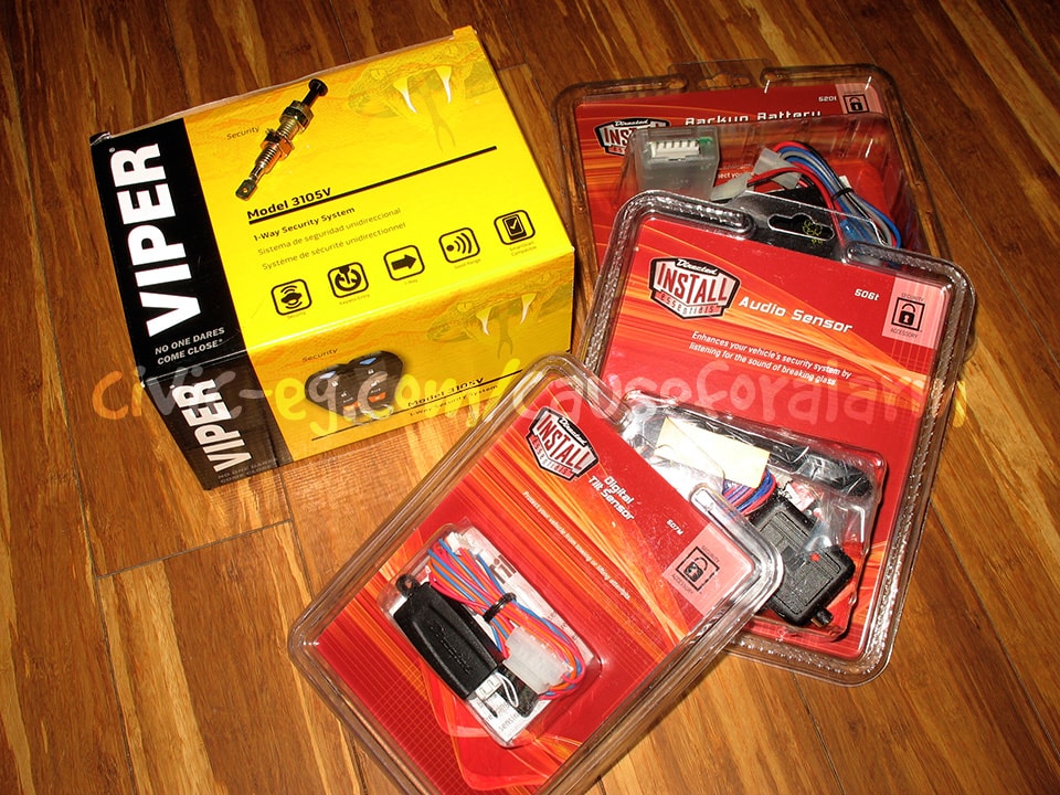
- Viper Alarm
- Tilt Sensor DEI 507M
- Battery Backup Module DEI 520T
- Glass Break Sensor DEI 506T
- Hood Pin Switch
- Supplies
- DEI 451M dual relay module
- Backup Battery Upgrade
- 18 gauge Stranded Wire
- 22 gauge Two Conductor Wire
- 1/4" Heat Shrink
- Solder
- Electric Tape
- Non-insulated Butt Connectors
- 3/4" Split Loom
- 1/4" Split Loom
- Diodes
- SPDT Relays w/harnesses
- Back Straps
- Speed Clips
- Metal Tapping Screws
The Process
- Install a Kill Switch
- Bench Prep the alarm
- Remove non-functioning alarm installation if present
- Install the peripheral components into the car
-
- Peripheral Components
- Siren and Hood Pin
- Start Kill
- Antenna, LED, Valet Button
- Doorlock Actuators
- Trunk Pop Actuator
- Test the full functionality of the alarm
Rip out that junk install
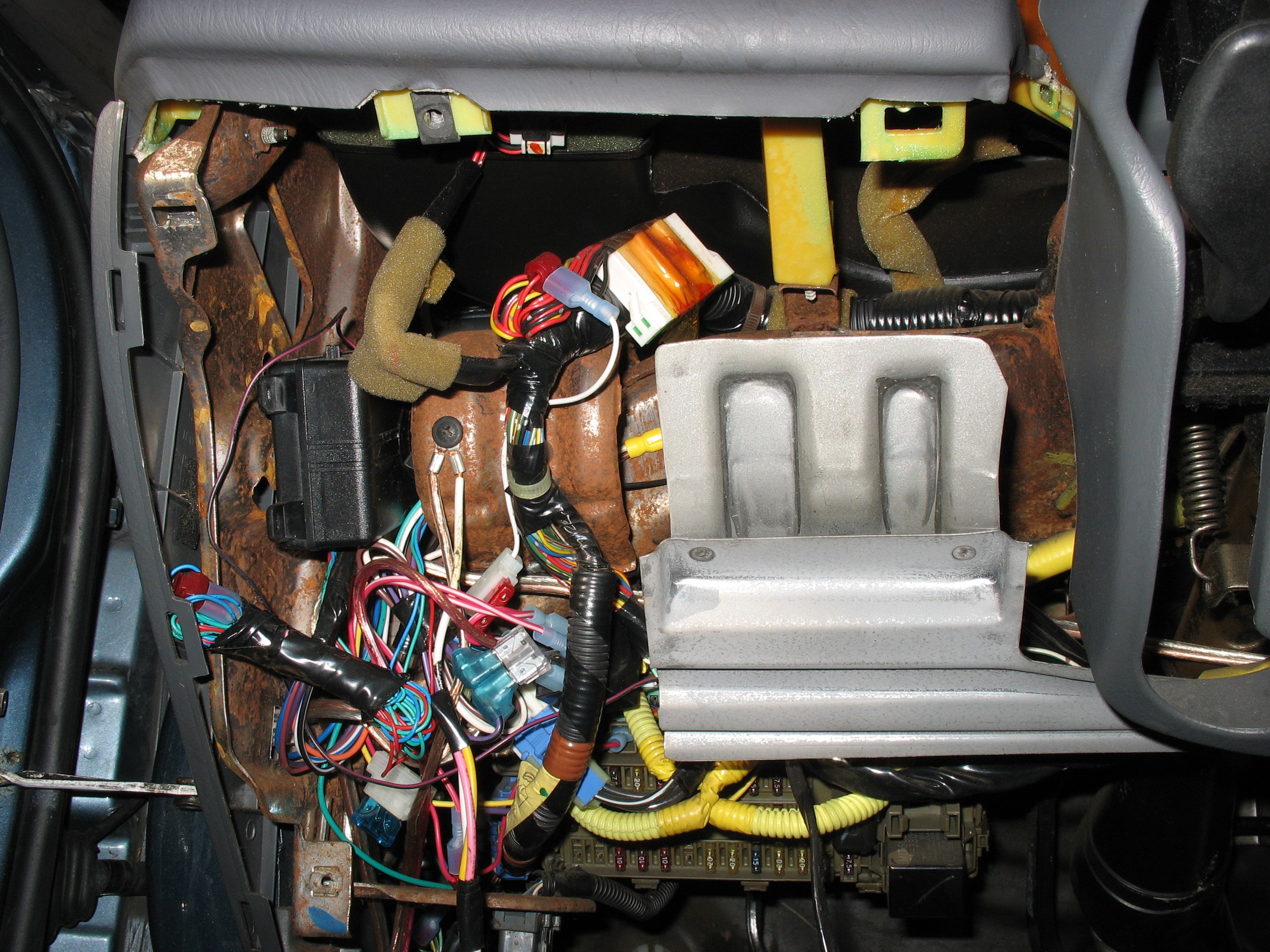
Alot of times you drop your dash panel and there's a rat's nest of an alarm installed there that the previous owner forgot about after losing the key fob. Pull the brain down and then unplug or cut each wire at the connection to the car. On your ignition harness your blk/wht starter wire will be cut and run through an aftermarket relay. Your car will still work with the alarm removed and the relay plugged into it's socket. You can clean it up and repurpose it as an 2nd start kill with your installation, or you can get a 12-10 gauge non-insulated butt connector and heat shrink and reconnect your starter wire.
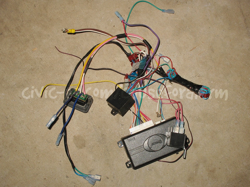
Alarm & Components Arrangement
Stack into a brick shape the alarm brain, battery backup and module, glass break sensor brain, doorlock 451M module, and optional trunk pop & driver's priority unlock 451M.
After the alarm is wired and tested, you can create a sheet metal box to house it. Scroll to the end for more information.
Alarm Main Harness
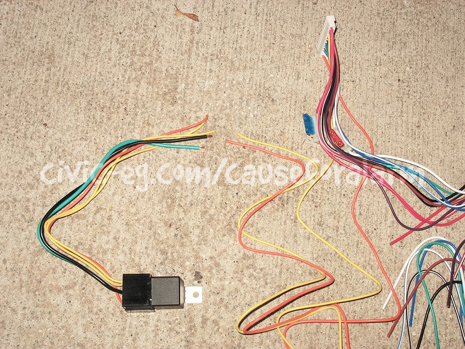
Cut the start kill relay yellow and orange wires to match the length of the others. The alarm will never be mounted the exact distance from the relay for these wires to be fully stretched out, and it's nasty to coil up any slack. Once everything is installed, these wires can be cut to length and reattached. Note that the yellow wire must go to the relay AND to the car's Ignition 12v.
RED/WHT is an optional Trunk Pop output (requires aftermarket doorlock actuator and a relay). I normally wire this to a 451M (scroll to Trunk Pop relay).
RED goes to the Gray on the 520T. First cut the inline fuse holder off the red wire, leaving an inch on it so it can be repurposed.
BRN is the Siren positive output (Red). Nothing is done to this wire other than to loom it with other wires that will be connected to the car.
YEL comes attached to the included Start Kill Relay, alongside the orange. Cut them to match the length of the other wires on the relay harness. Then run this in the loom of wires to be connected to the car.
GRN and VIO are for door triggers, and you never use both on one installation. Hondas are all negative trigger, so green is used and violet should be de-pinned.
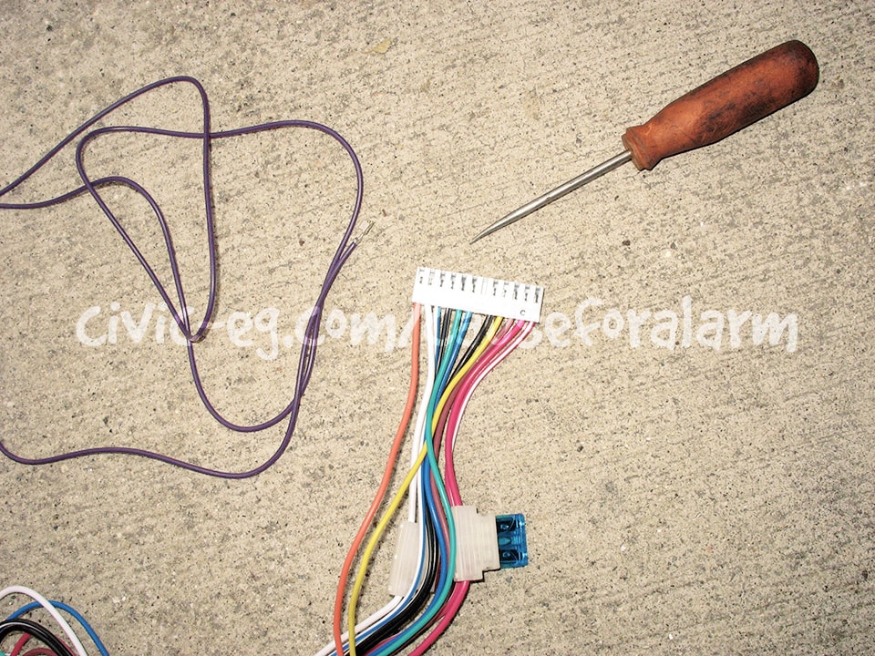
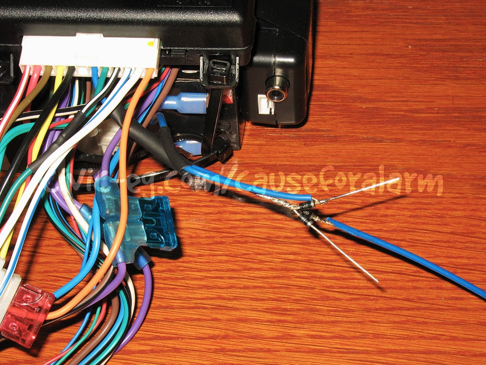
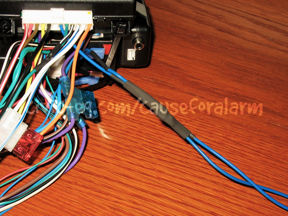
BLU is a negative alarm trigger intended for the wire that illuminates the trunk open warning light on the dash. Using diodes, you need to branch this wire into three isolated triggers: The trunk, an added hood pin, and the 520T's battery trigger. The non-striped end of the diodes are twisted together and connected to the blue wire on the alarm. Then each individual trigger connects to the striped end of a diode.
BLK/WHT is for domelight control. On the mid level and above alarms this connection is simple. However, if the installation guide lists the BLK/WHT wire's output in mA, then it requires a relay. Otherwise you can tap it into the green door trigger wire. The domelight feature is nice to have as it will light your interior when you disarm the alarm or when you park the car.
WHT/BLU is an optional aux output, rarely used except for Driver's Priority Unlock. If you're not doing that, then de-pin and remove it. Otherwise, wire it to a relay or a 451M.
WHT is positive Parking Light Output by default. Do not change the pin or fuse that sets this to positive. This wire should be loomed with the other wires connecting to the car.
ORN is connected to the included Start Kill Relay along with the yellow wire, and should be cut for now.
BLK needs a ring terminal crimped on so it can be grounded to the chassis on an existing bolt or with a metal tapping screw and a lock washer. There are Many grounds in this install, so gather them all together into a single, 10 or 8 gauge ring terminal.
- List of Grounds
- Alarm BLK
- DEI 520T BLK
- Siren BLK
-
- Doorlock Actuators' Grounds w/ 451M
- Doorlock Actuator Unlock relay (87A) or 451M BRN/BLK
- Doorlock Actuator Lock relay (87A) or 451M WHT/BLK
- Driver's Priority Unlock (87A)
Repeating Wire Colors
Do not mix up the various blues and greens or the blu/blk grn/blks. It can be helpful to label these on a small piece of masking tape and wrap it at the end of each of the common colors so you don't have to trace them after they've been loomed.
- Repeating Wire Colors
- Green Door Lock (22awg)
- Green Negative Door Trigger
- Blue Door Unlock (22awg)
- Blue Trunk Trigger
- Blue (or whichever color you choose) Hood Pin
- Blu/Blk 451M Output x2
- Grn/Blk 451M Output x2
Keyless Entry Doorlock Harness
If your car has power doorlocks, and you're not interested in Driver's Priority Unlock or bypassing the OEM doorlock module, then simply run the 2-pin 22 gauge BLU and GRN wire harness into the loom of wires to be connected to the car.
If your car has power doorlocks and you want Driver's Priority Unlock, then run a 451M, a third relay, and bypass the OEM doorlock module in the driver's door.
If you're adding door lock actuators to a manual lock car, then one 451M can run all the doors. It works the same if they're OEM or aftermarket actuators.
If you don't convert a manual door car to Keyless Entry, you aint livin'.
Adding Doorlock Actuators
When used for aftermarket door lock actuators, the 451M (Right) plugs in place of the power doorlock harness (Left) included with the alarm.
- 451M w/ Added Doorlock Actuators
- VIO/BLK goes to battery power Constant 12V
- BRN/BLK goes to chassis ground
- WHT/BLK goes to chassis ground
- BLU/BLK goes to unlock on all actuators
- GRN/BLK goes to lock on all actuators
Driver's Priority Unlock
This is a useful feature to prevent "Sliding". That's when you're at the gas station and a thief opens your passenger door and steals your purse. Driver's Priority Unlock means that only the driver's door unlocks unless you hit the Unlock Button a second time. It's also useful in extending the life of your passenger doorlock actuator motors.
This requires moving the passenger door actuators' unlock wires to a third relay. The driver's actuator stays the same and all lock wires stay the same.
- Driver's Priority Unlock relay
- 86 WHT/BLU on alarm main harness (reprogrammed to 2nd Unlock Output)
- 85, 87 goes to Constant 12V
- 87A goes to Chassis Ground
- 30 goes to all actuators' unlock wires
Alarm w/ Doorlock Relays Onboard & Car w/ Power Doorlocks
This situation occurs when you are installing a Remote Start Viper Alarm onto a car with power doorlocks. These higher end alarms have doorlock relays onboard, which is overkill if you have power doorlocks.
- VIO goes to chassis ground
- BLU/BLK goes to the car's Unlock wire
- BRN/BLK is not used and can be de-pinned
- VIO/BLK goes to chassis ground
- GRN/BLK goes to the car's Lock wire
- WHT/BLK is not used and can be de-pinned
- BLK/WHT is an onboard Domelight Relay and goes to chassis ground
About 451M "Door Lock Interface"
The 451M is simply two small relays on a circuit board, nicely prewired. There's nothing stopping you from repurposing it to do two start kills, or to control your trunk pop actuator and driver's priority unlock.
On my manual doorlock EG, I added OEM actuators to the two doors. That requires one 451M. A second 451M controls the driver's priority unlock, and also powers an aftermarket actuator on the hatch. A 3rd 451M controls two start kills. Using three 451Ms is a huge convenience and time saver versus having to individually mount six relays, each requiring 4-5 spade connectors and color-coded wires.
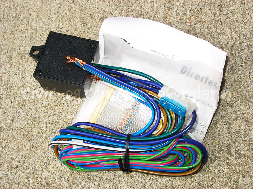
These resistors aren't needed for anything we're doing here, but they could be useful for other things (simulating sensors, installing LEDs, etc).
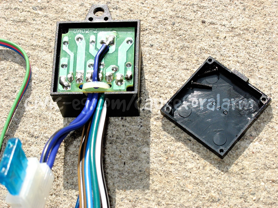
The traces make it easy to follow the color pairing to each relay. There's no need to open the module. This is purely for illustrative purposes.
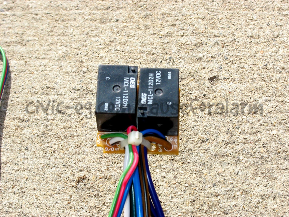
See? Two little relays. Aren't they cute?
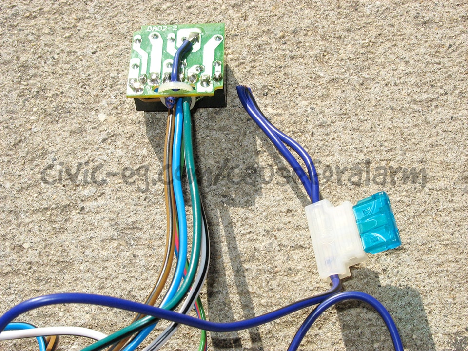
For some things, these purple wires aren't needed, so I cut them or desolder them depending on my mood. Then I can reuse this handy three-way inline fuse holder for something else.
Trunk Pop relay & actuator
If you'd like your trunk to pop open when you hold the Aux button for 2 seconds, you'll have to add a relay and mount an actuator near the trunk latch. You use a doorlock actuator and wire it to fire in one direction, with a small spring to assist in pulling it back again.
"Trunk Pop Actuators" are far too powerful and bulky for this purpose. Use an aftermarket doorlock actuator!
- Trunk Pop Relay Wiring
- 86 RED/WHT alarm main harness
- 85, 87 RED Constant 12V on DEI 520T
- 30 goes to actuator
- actuator's other wire goes to Chassis ground
Actuators are reversing polarity meaning they move one direction with positive and negative, and the opposite direction when those are flipped.
Whether pulling or pushing pops the trunk is dependent on which direction the actuator is mounted. We only need it to move one direction, then automatically go back to a resting position in the other direction. So we can have one actuator wire always grounded, and the other connected to the relay to get a positive pulse when you hold Aux.
DEI 520T Battery Backup
- RED goes to Constant 12V battery power on the car. Many other wires tap into this one.
-
- These wires branch off the 520T's Red
- Car's Constant 12V
- VIO/BLK on 451M Doorlock Module or 85, 87 relays
- 85, 87 Driver's Priority Unlock relay
- 85, 87 Trunk Pop relay
- GRAY goes to the RED on the alarm harness.
- BLACK joins all the other BLKs in a ring terminal to chassis ground.
- BLUE goes to one of the diode branches coming off BLU on the alarm harness.
Antenna / LED / Valet Button
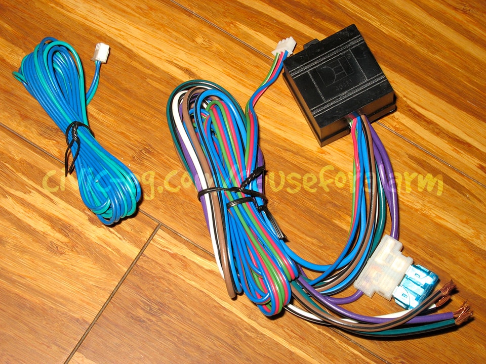
Mid level and above Viper alarms combine these all onto the antenna. The entry level Vipers require each to be mounted independently. Run this harness or harnesses in the loom of wires connecting to the car.
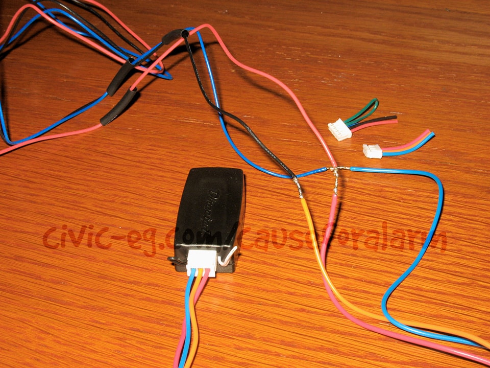
Sensor Harness
The 506T Glass Break Sensor comes with a Y harness that plugs into the alarm. The center 4 pin harness (no loop) plugs into the alarm and the 3 pin harness plugs into the 506T. Cut off the other 4 wire plug, cut the smaller 3 pin plug off the Tilt Sensor harness, and wire them together.
Pay close attention to the two 4 pin plugs on the Y harness. The sensor plug has GRN and BLU looped together and the center of the Y doesn't. You MUST plug the center plug into the alarm or else the Tilt Sensor will never trigger the alarm!
- 507M Tilt Sensor
- BLU to BLU on the 506T harness
- ORN to BLK on the 506T harness
- RED to RED on the 506T harness
Connections to the Car
Bench prepping gets nearly all of the difficult wiring out of the way. All that should be left are the Antenna, Tilt Sensor harness, the Siren and Hood Pin connections, Grounds, and the wires connecting to the car.
- Orange - Start Kill relay
- White - Parking Lights
- Green - Door Trigger
- Blue (Diode) - Trunk Trigger
- Yellow - Start Kill relay and Ignition 12V
- Brown - Siren positive
- Black, WHT/BLK, BRN/BLK - Grounds for alarm brain, 520T, 451Ms
- Blue or Gray (suggested) (Diode) - Hood Pin
- Antenna
- Tilt Sensor Harness
- Glass Break Sensor Mic
- BLU/BLK - Unlock Actuators
- GRN/BLK - Lock Actuators
- BLU/BLK or GRN/BLK - Trunk Pop Actuator
Mounting Box Design

When designing the mounting box, leave 1/4 inch around all sides for the adjustment knobs and side harnesses. Leave at least 1/2 inch in the front for the main harness and 451M harnesses. Also leave space to line the inside of the box with cardboard in all directions.
