
- Wed Oct 27, 2010 9:01 am
#220240
A Member frome here asked me to make an extra thread here from my engine built.
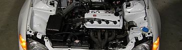
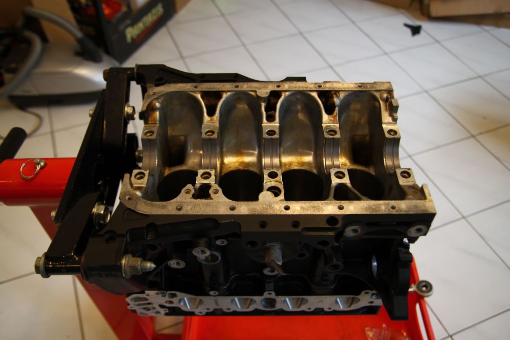
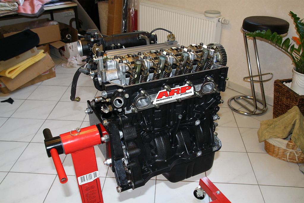
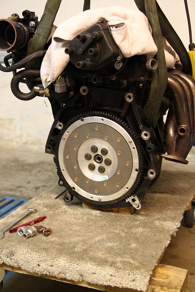
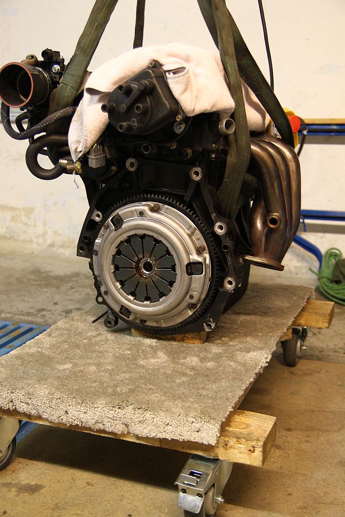
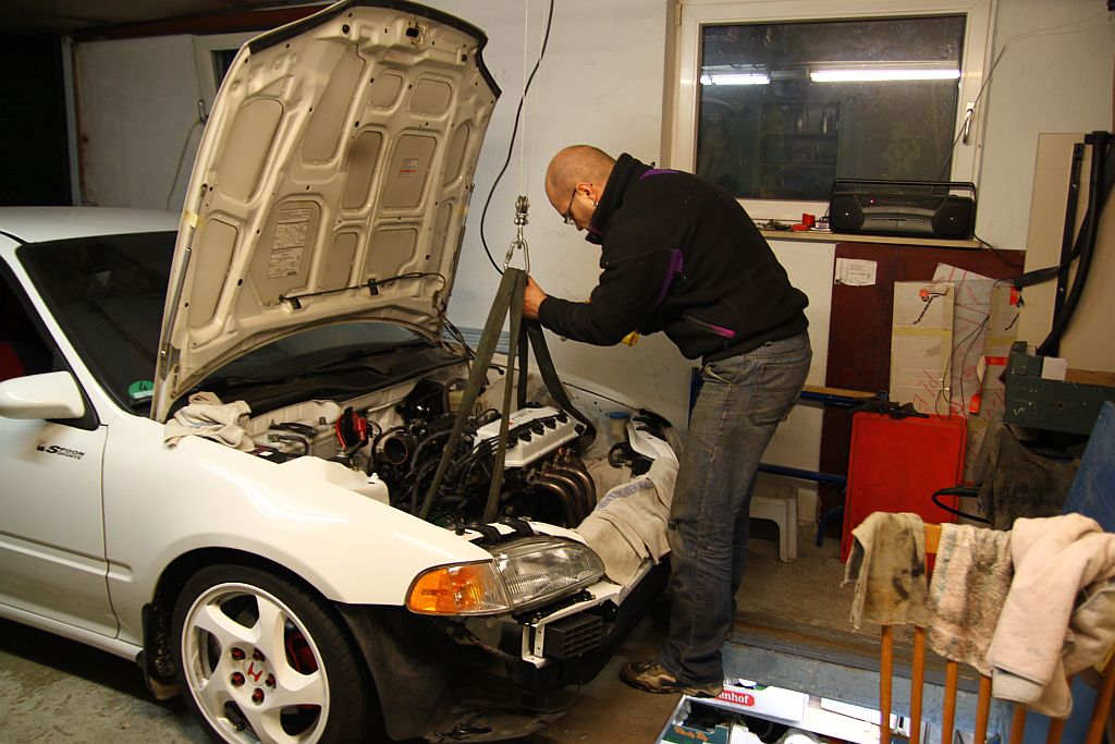
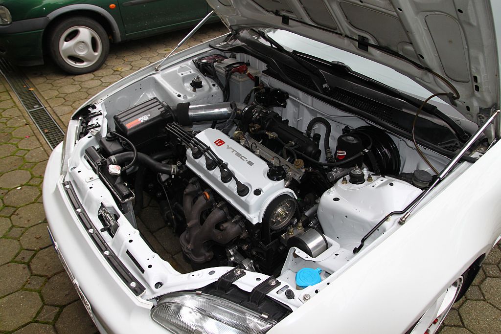
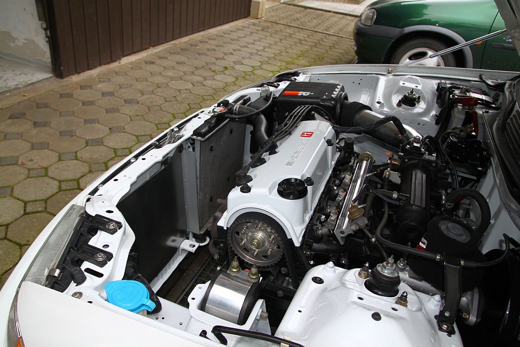
I started my D15z1/D16z6 frankenstein built.
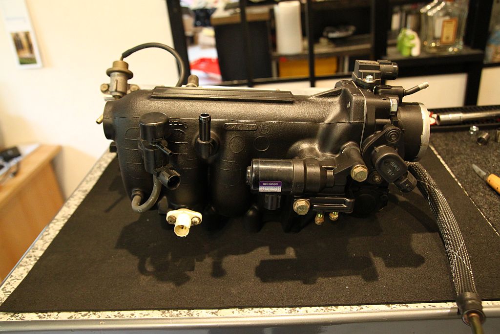
Means z6/9 short block with z1 head, z6 IM, z6 TB, 4-wire O², Modified P28 ECU, 240cc Inj, VX trani. The head is going to be ported and milled by .002''. Disassembled bouth engines and started cleaning.
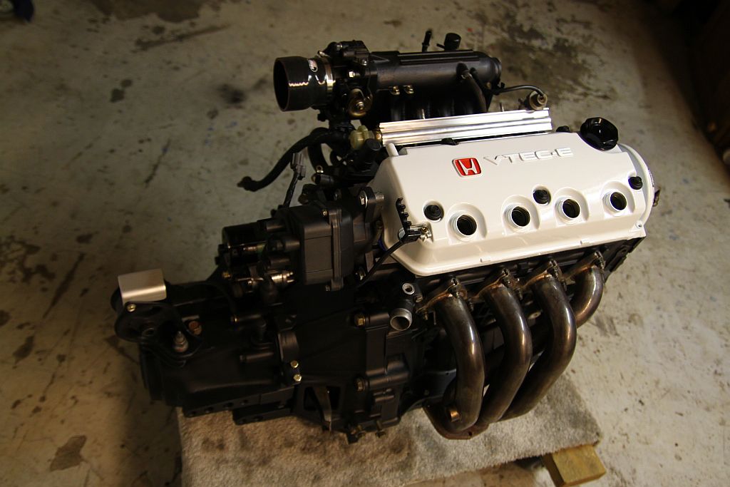
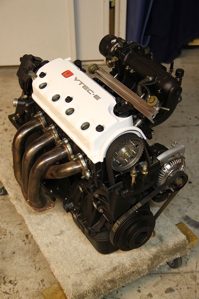
here are some pictures:
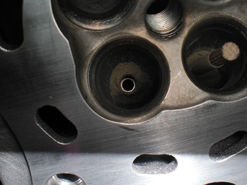
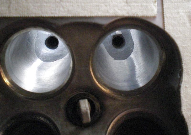
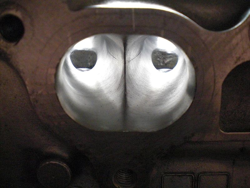
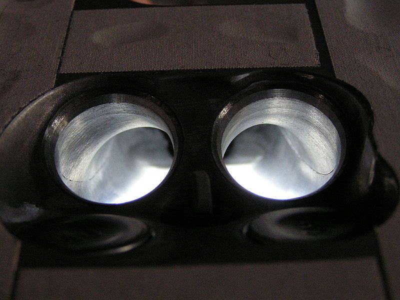
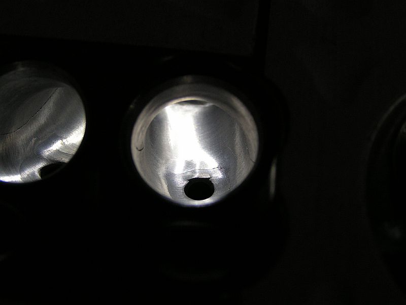
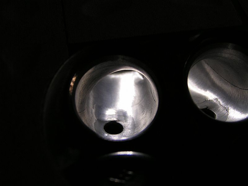
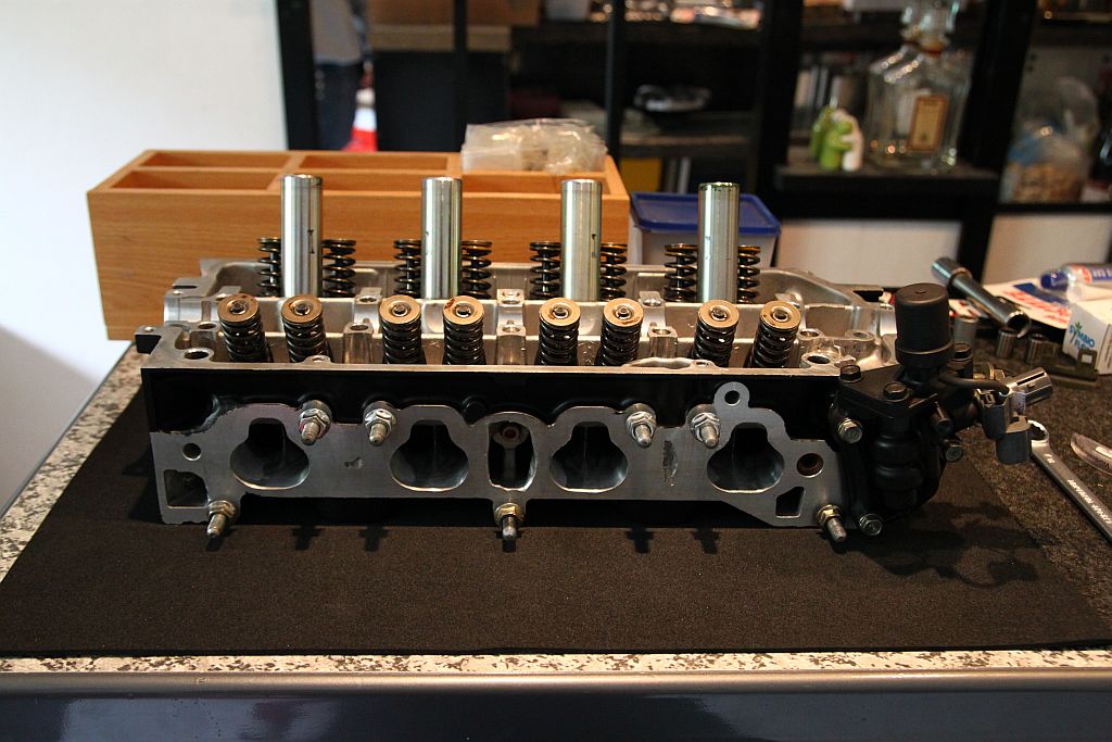
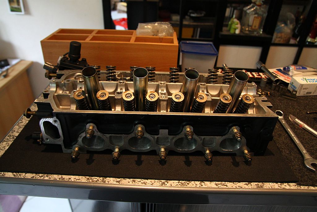
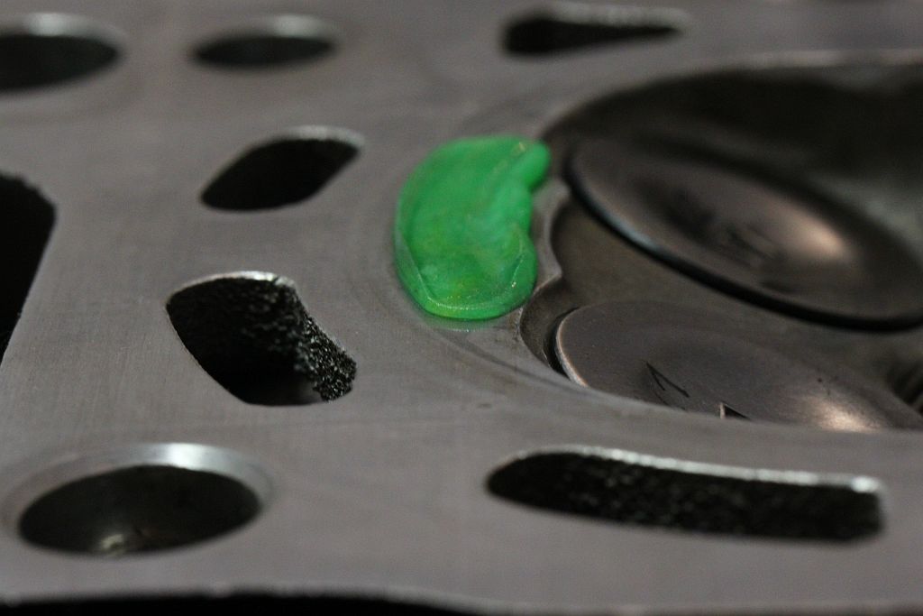
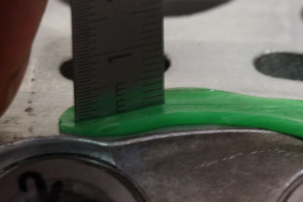
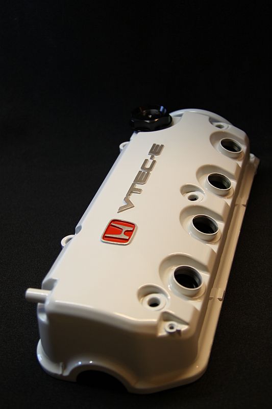
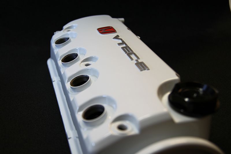
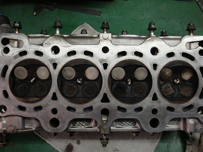
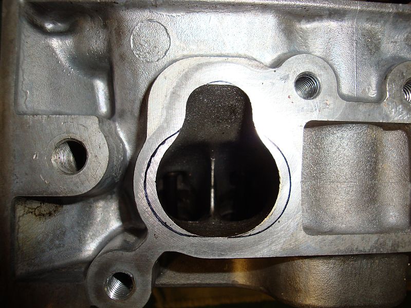
VX D15z1 swirl head


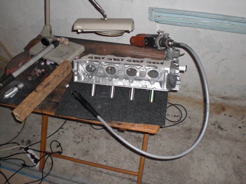
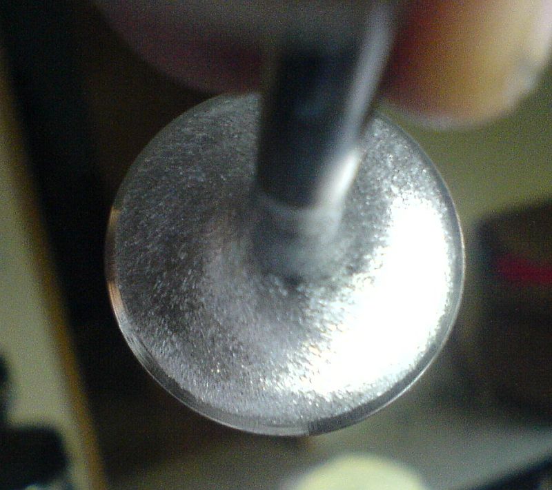
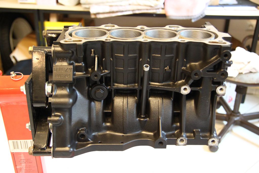
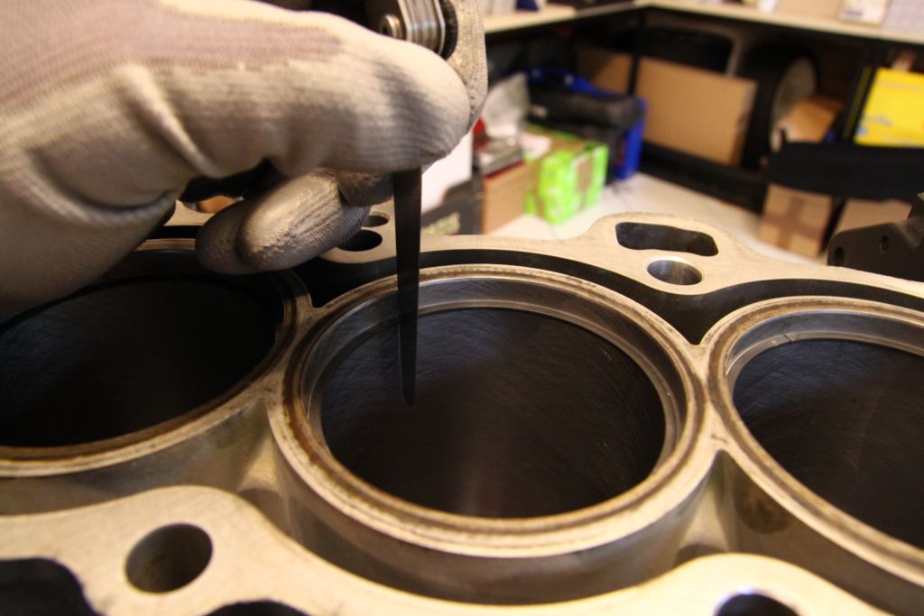
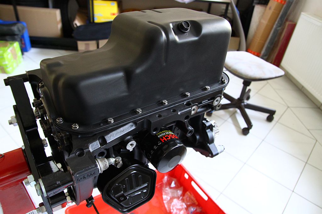
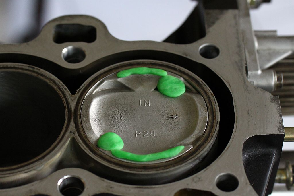
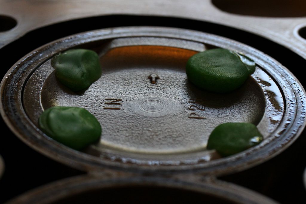
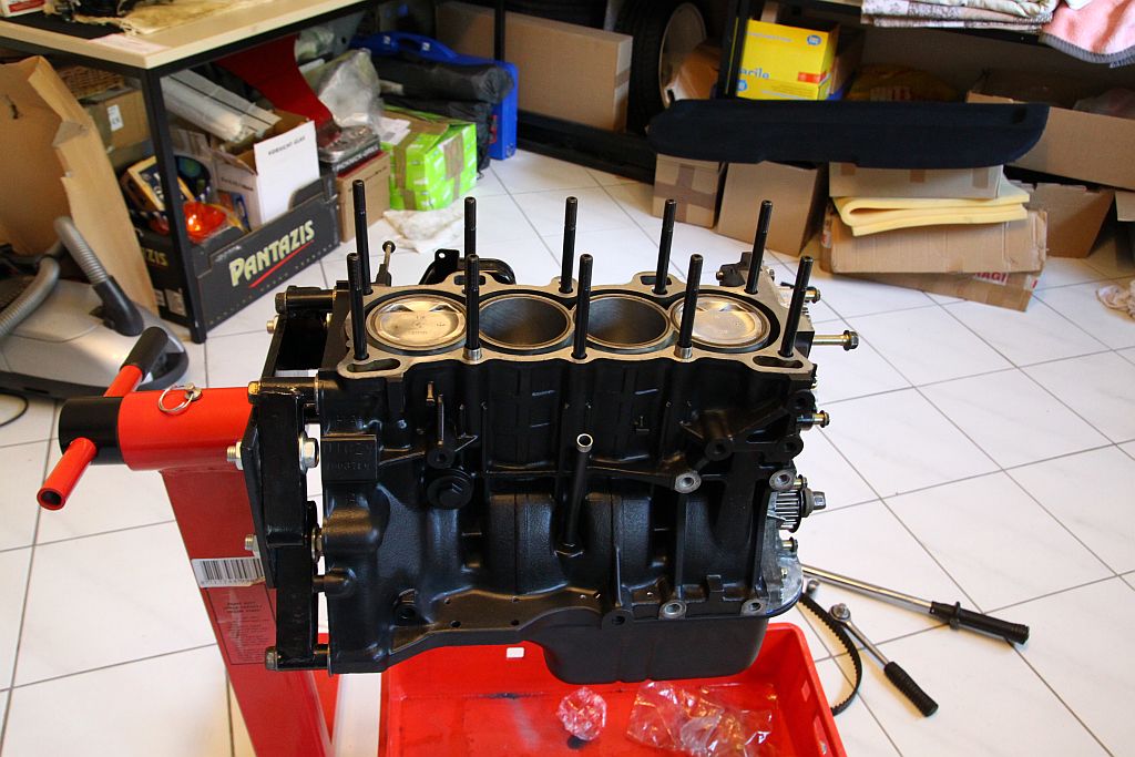
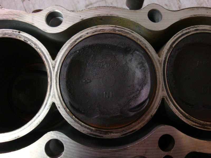
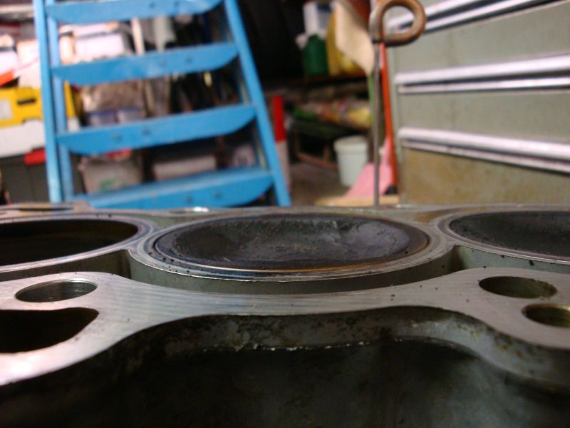
VX D15z1 piston in block
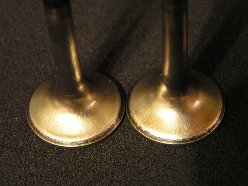
comparison z6 / z1 head

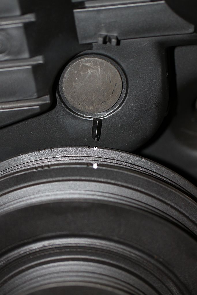
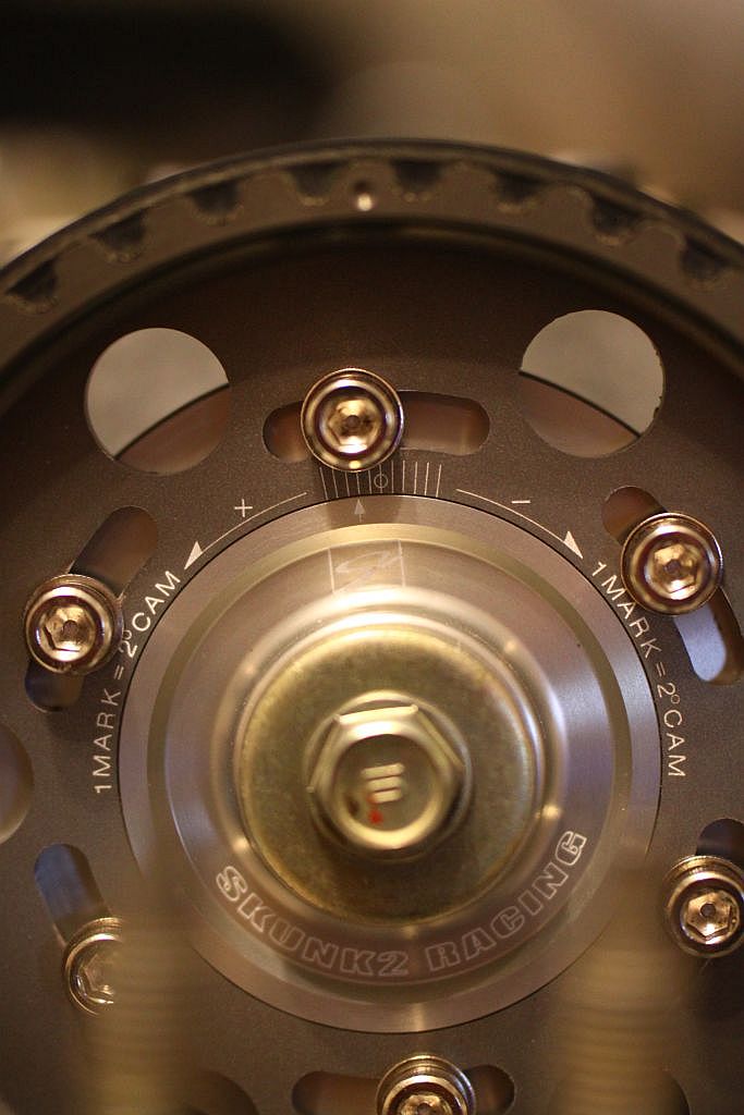
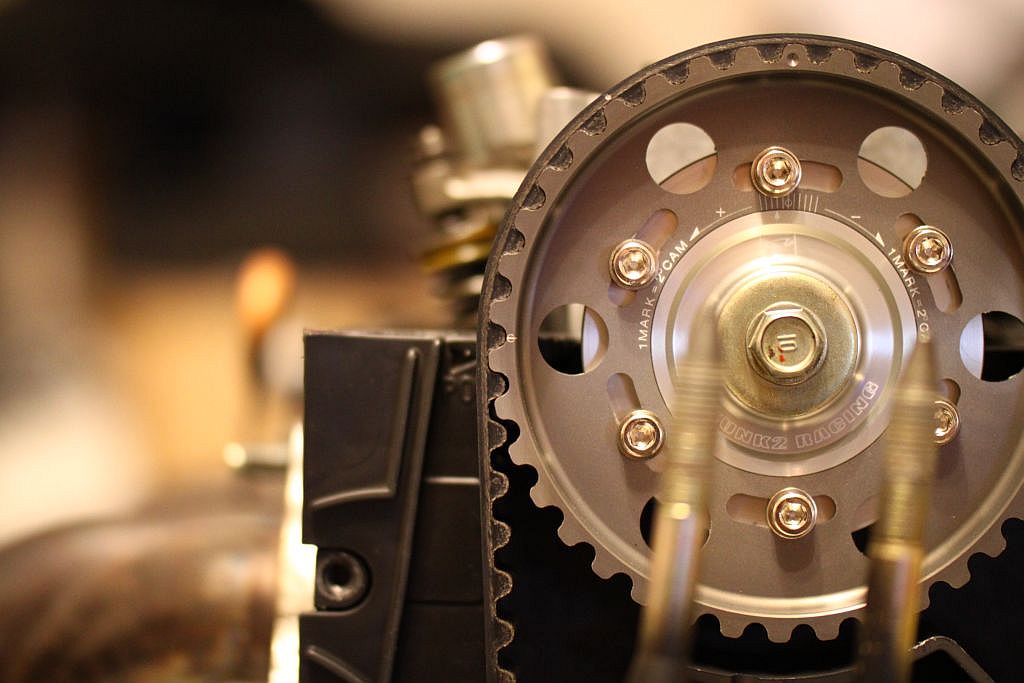
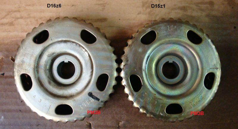
comparison z6 / z1 cam gear (same)
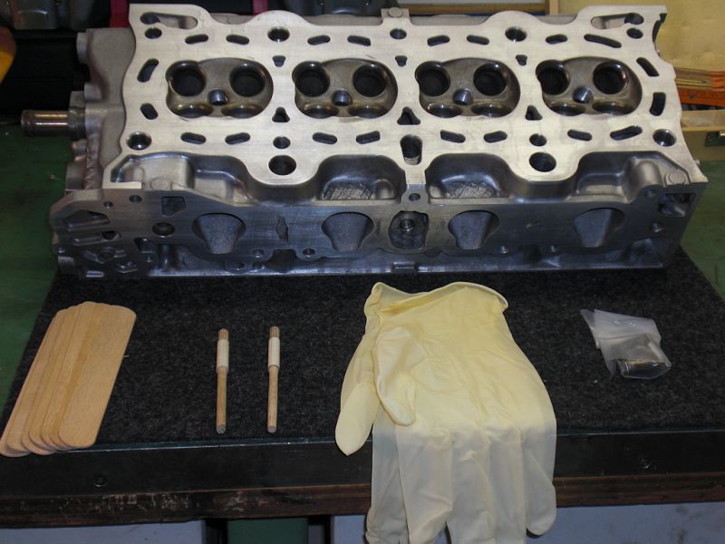
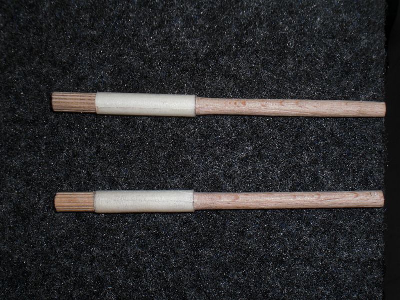
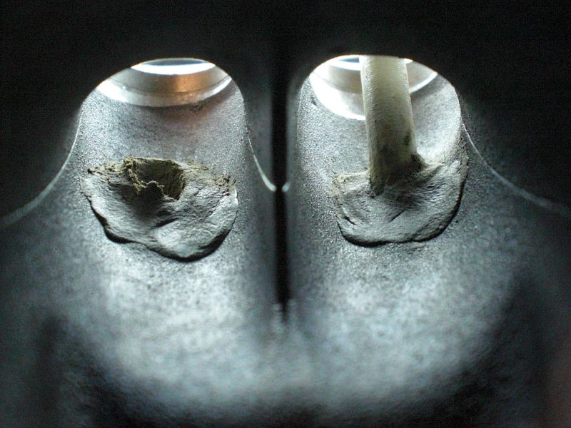
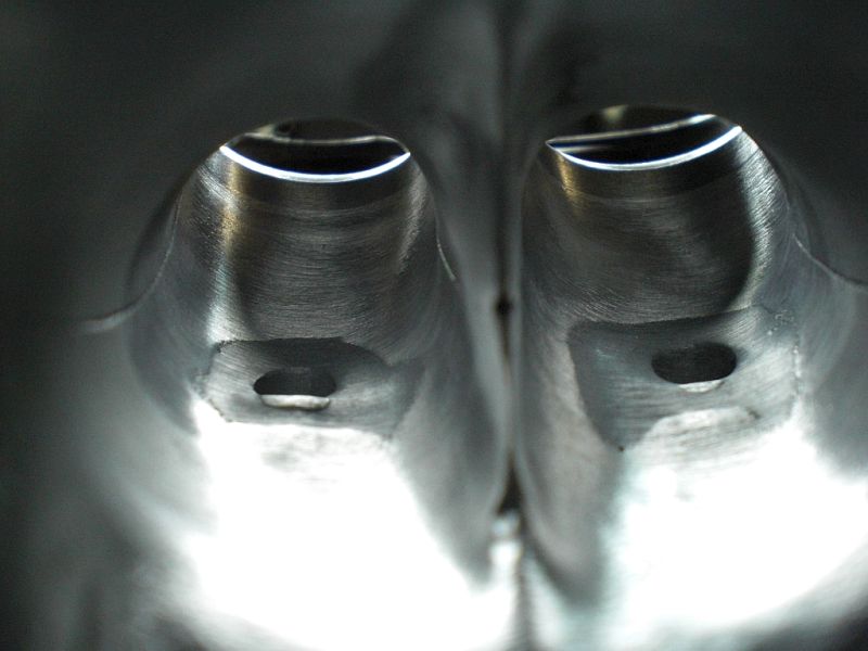
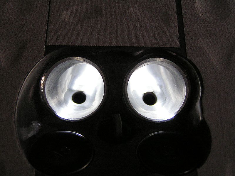
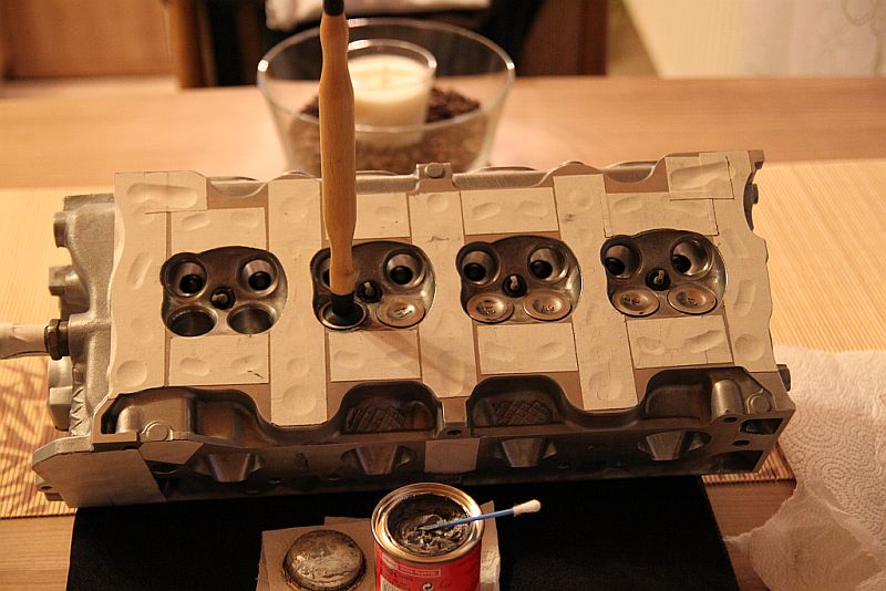
this will be the shape when it's ported
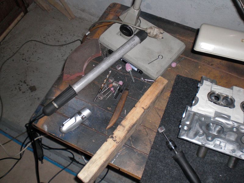
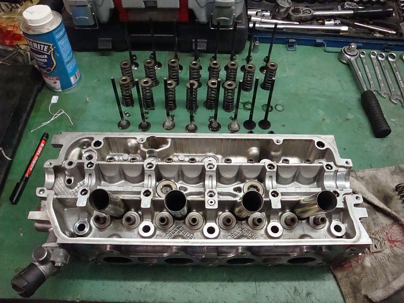
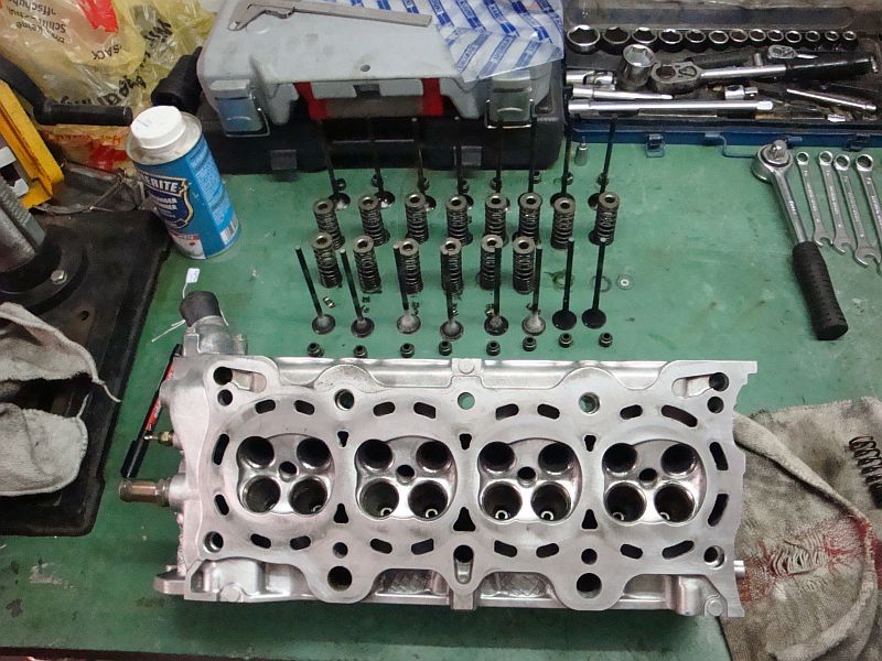
head complet disassembled and cleaned
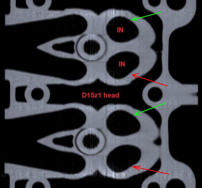
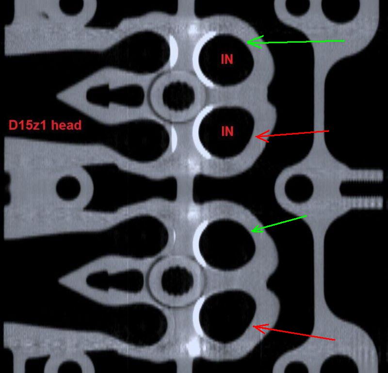
I had my z1 head in the Computertomograph to see how the ports are shaped and if there are some cracks. The head is in perfect condition!
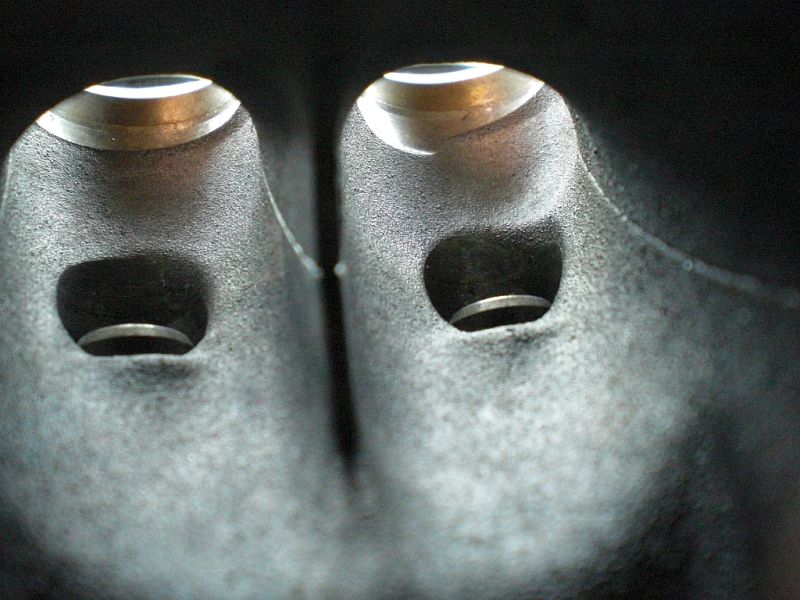
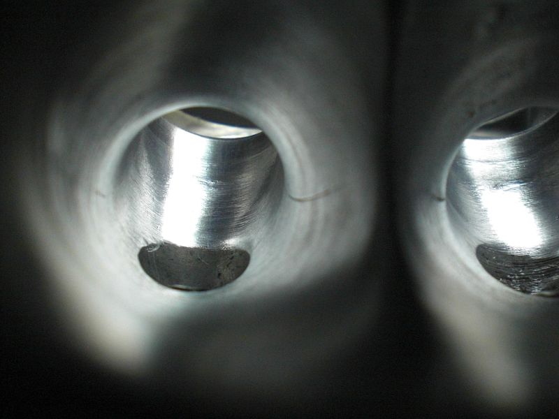
Here you can see the slight difference between the swirl (lower in port) and the non swirl port (upper in port)
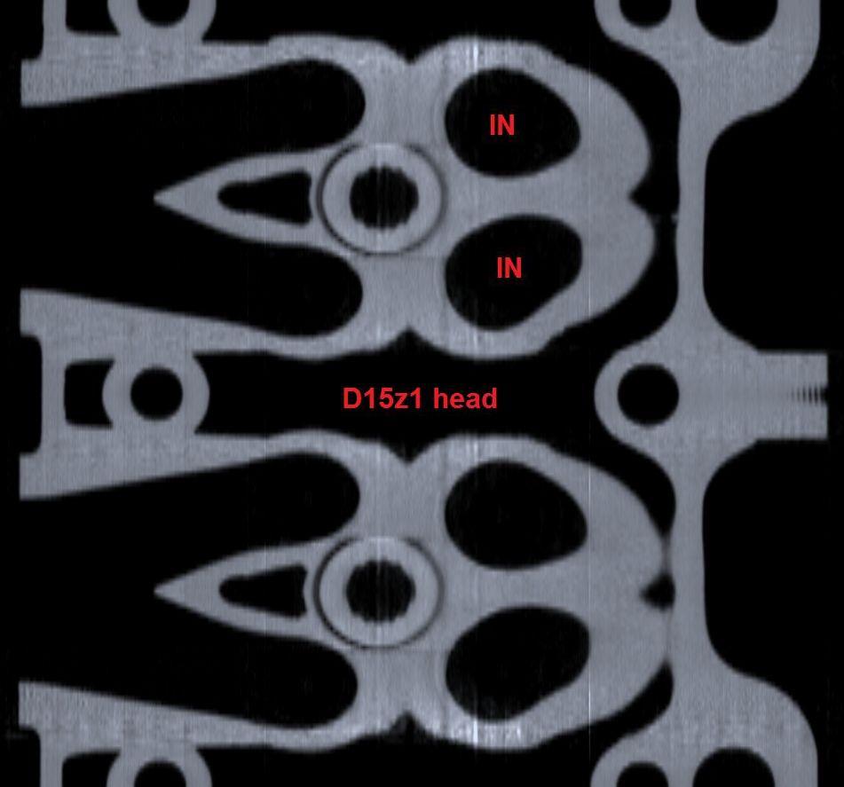
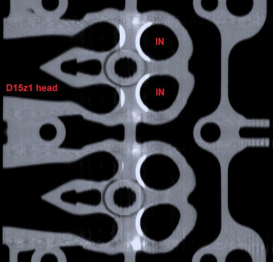
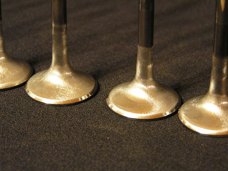
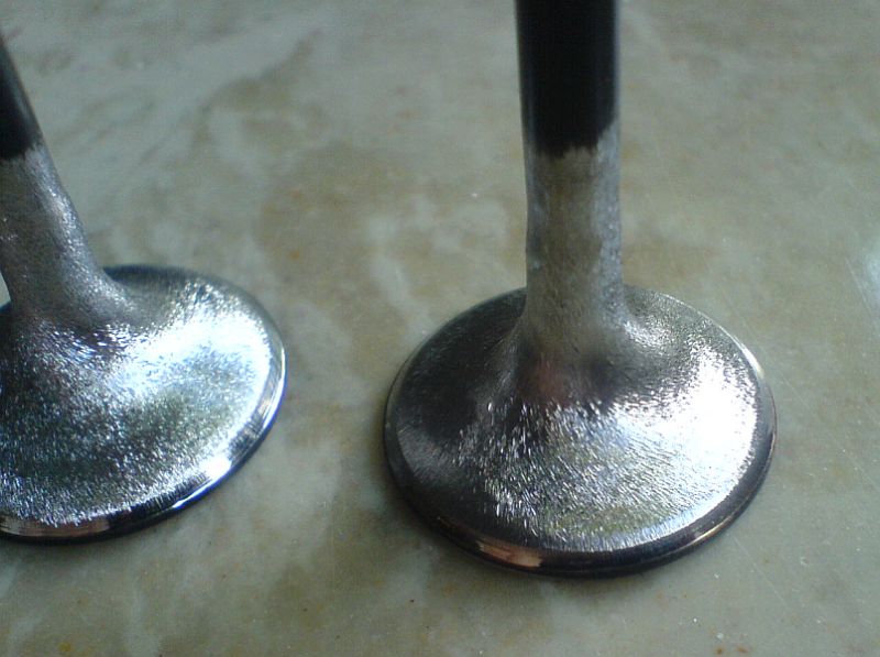
Intake
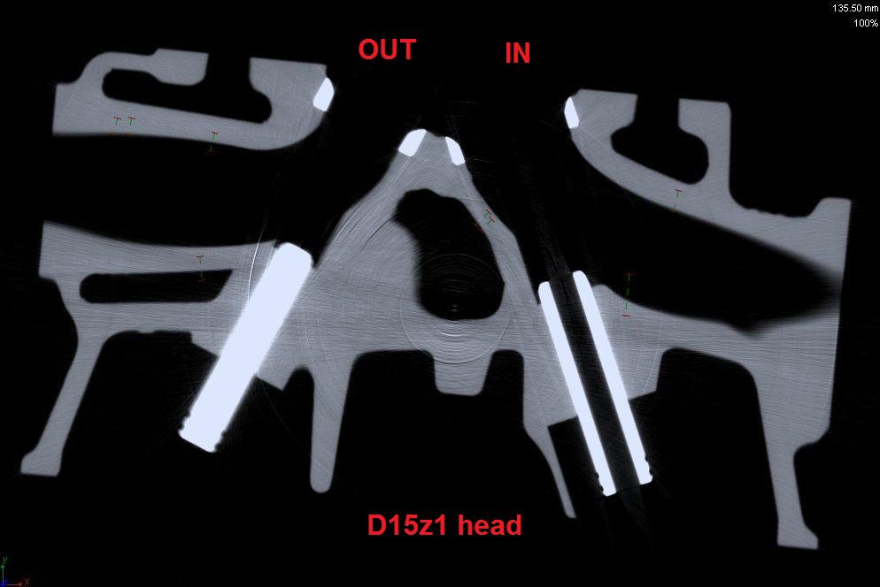
Outtake

I started my D15z1/D16z6 frankenstein built.
Means z6/9 short block with z1 head, z6 IM, z6 TB, 4-wire O², Modified P28 ECU, 240cc Inj, VX trani. The head is going to be ported and milled by .002''. Disassembled bouth engines and started cleaning.
here are some pictures:
VX D15z1 swirl head
VX D15z1 piston in block
comparison z6 / z1 head
comparison z6 / z1 cam gear (same)
this will be the shape when it's ported
head complet disassembled and cleaned
I had my z1 head in the Computertomograph to see how the ports are shaped and if there are some cracks. The head is in perfect condition!
Here you can see the slight difference between the swirl (lower in port) and the non swirl port (upper in port)
Intake
Outtake
Last edited by robster on Wed Feb 09, 2011 5:32 pm, edited 2 times in total.