
F23 Swap Guide
Out Now!
Stealth Car Alarm Install
1990-1993 Acura Integra
Alarm Bench Prep
OEM Wire Colors
| WIRE | COLOR | LOCATION |
|---|---|---|
| 12 VOLT CONSTANT | Option Output A OR C | Under dash fusebox |
| STARTER | BLK/WHT | Under dash fusebox or engine harness firewall grommet |
| IGNITION | BLK/YEL | Under dash fusebox or engine harness firewall grommet |
| PARKING LIGHTS (+) | RED/BLK 1 dot | Driver's running board |
| DOOR TRIGGER (-) | DK GRN/RED | Driver's running board |
| TRUNK TRIGGER (-) | GRN/BLK 2 dots | Driver's running board |
| POWER LOCK (-) | GRN/WHT | Under Driver's kick cover |
| POWER UNLOCK (-) | GRN/RED | Under Driver's kick cover |
*You must put a fuse in #13 to use C as a Constant 12v output. ALL WIRES MUST BE VERIFIED WITH A MULTIMETER.
What is a "Stealth Install"?
The standard type of alarm install you get when you pay a professional to install your alarm is easily overcome by thieves. In order for an alarm to be effective, the control unit must be invisible and undetectable, the siren must be hidden and inaccessible, all wiring should be concealed, the alarm should have its own backup battery, and the alarm must be able to detect all types of intrusion.
The Process
- Install a kill switch
- Bench prep the alarm
- Test on the bench
- Install alarm peripherals into the car
- Disassemble the interior
- Mount the alarm
- Wire the peripherals to the alarm
- Locate, verify, wire the vehicle connections
- Wire the start-kill
- Test the alarm, adjust sensors
- Fully reassemble the vehicle
- Test again
Alarm Peripherals
The best way to start the install is to get all of the alarm's peripherals out of the way. "Peripherals" includes sirens, the antenna, the valet button and LED, all the sensors including the hood pin, and the backup battery.
Antenna
Range is critical for two-way paging alarms. For the best possible range, mount the antenna up high and tuck any excess length loosely in the headliner. Never tightly bundle up the wire or range will suffer. Another aspect of antenna range is the strength of the power and ground connections.
LED
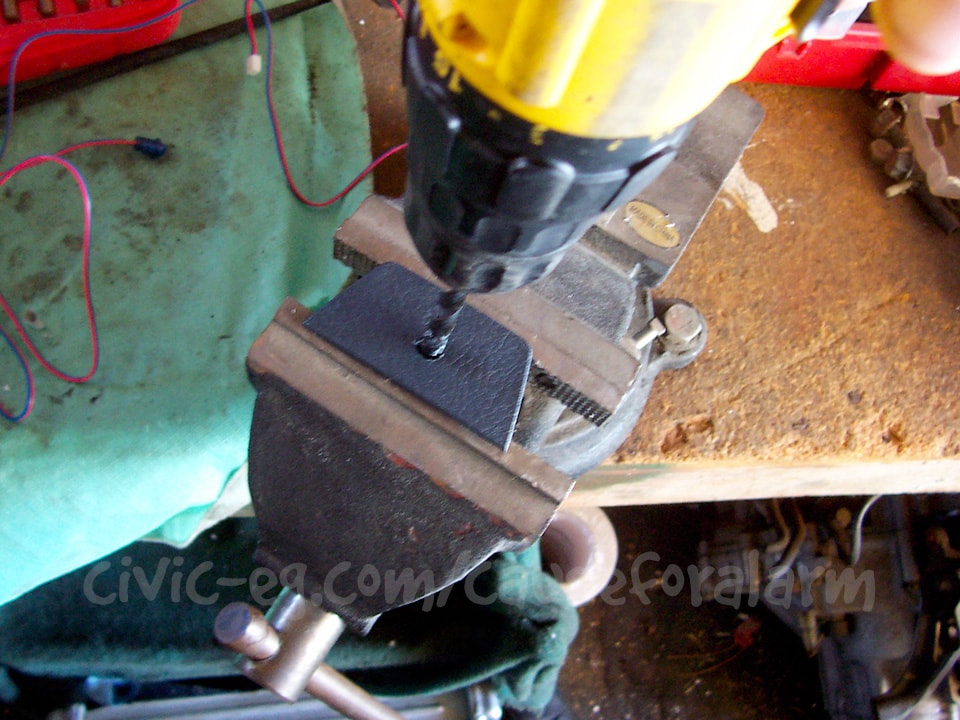
The best mounting place for the LED is a pop out panel that is easily visible from outside the vehicle. Drill a hole using a 17/64 or 1/4 bit. The manual says 9/32, but then the LED will be loose so use the next size smaller and a round file. Press the LED in on a soft surface like a carpeted work bench.

The only bad thing about doing a stealth install is that you'll have to extend the 22 gauge LED, valet, and motion sensor wires. I keep junkyard LEDs available so I can cut off the LED and extend the wires.
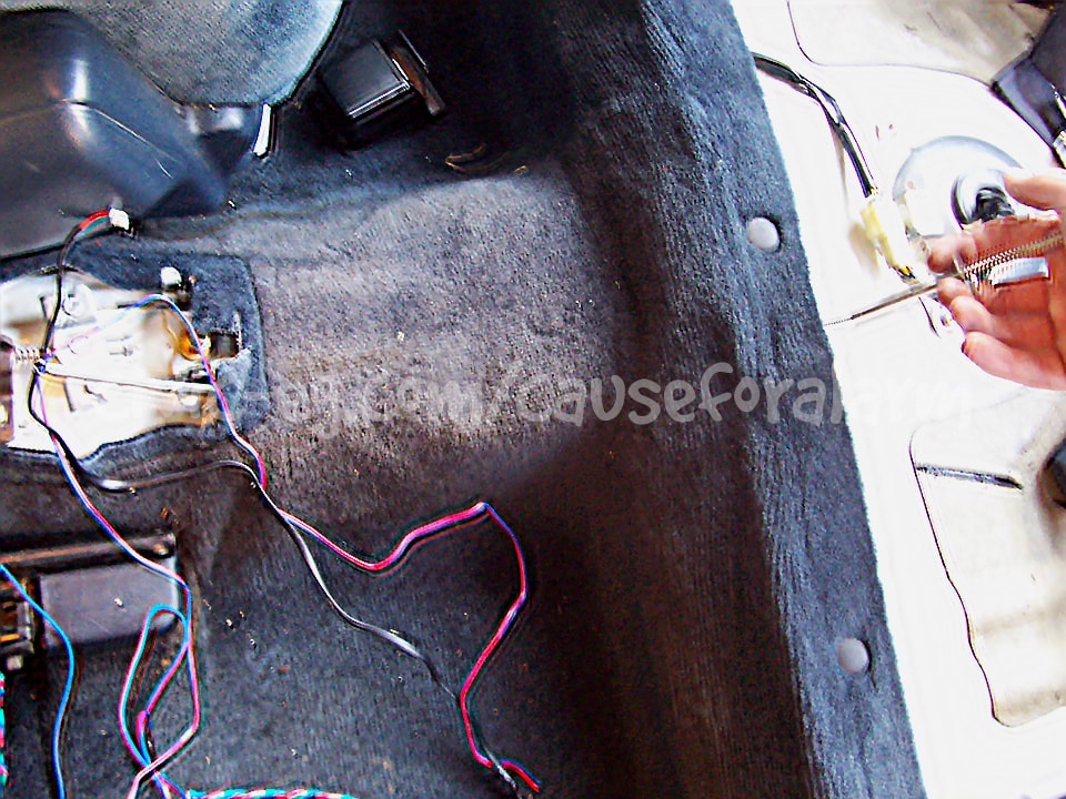
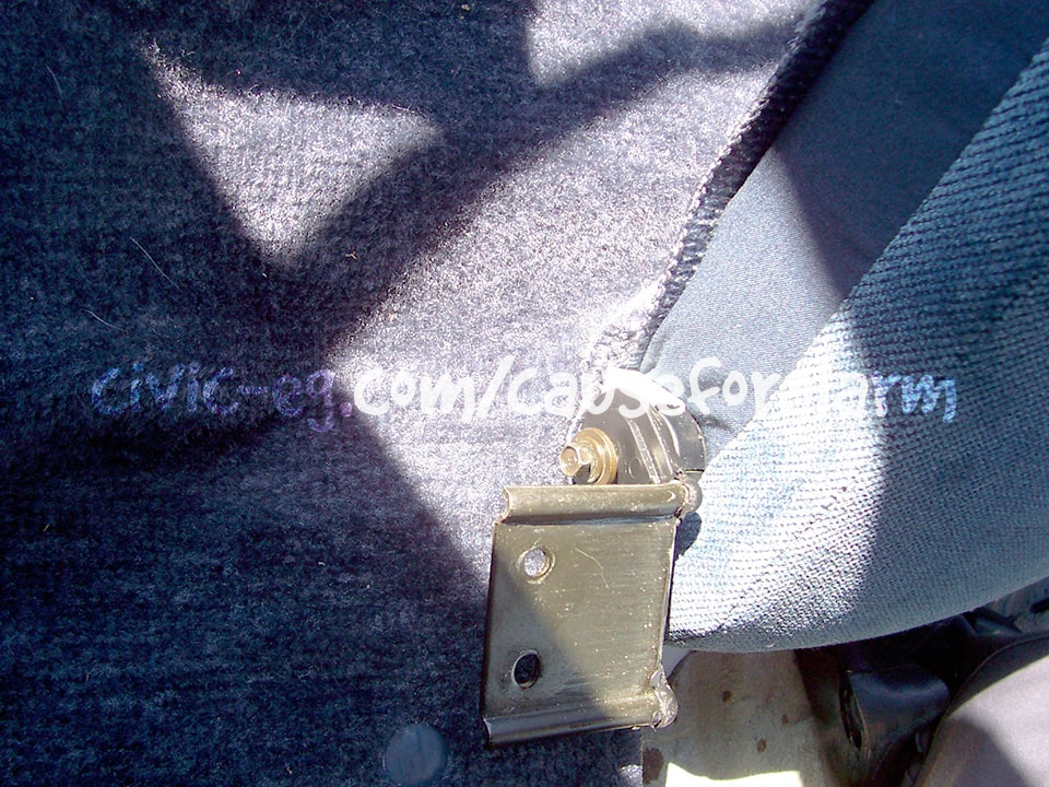
The grappling tool is a good example of how having the right tool at the right time is a lifesaver. Use it to run wires under the carpet between the ebrake and the rear seat.
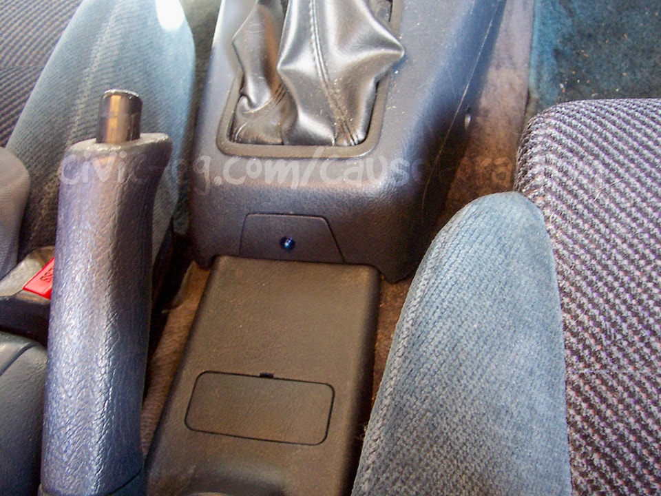
Valet Button
You can mount the valet button the same as you would an LED, except you want to hide it. I usually just wait until the install is finished, program whatever options I want, and then remove the valet button. You can put the alarm into valet by hitting lock, unlock, lock quickly in sequence on the remote.
Hood Pin
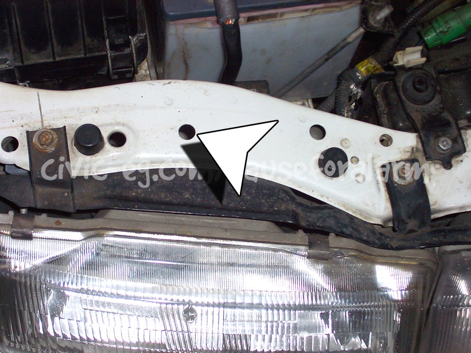
92-93
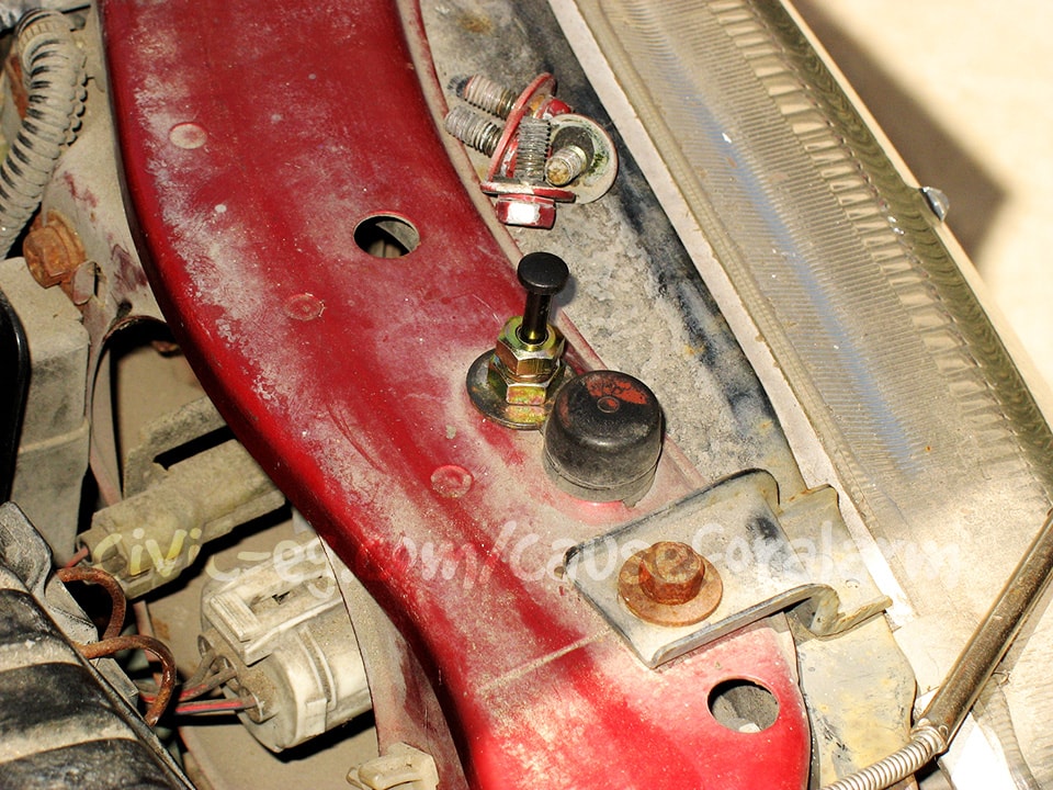
90-91 can use either hole
Non remote start alarms don't come with a hood pin, but you can get them online. Mount it and run it's wire into the interior. I typically use a gray wire for the pin trigger, and a black wire on a ring terminal to ensure the switch is sufficiently grounded. They gray hood pin trigger goes to the blue negative trigger input on the alarm, diode isolated from the trunk and battery backup triggers. The black ground ties in to the alarm blk ground.
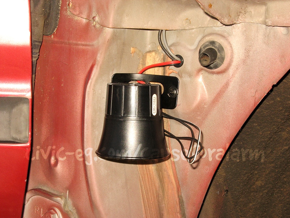
Siren
Install the siren in the engine bay using metal tapping screws. Cover the siren wires with split loom and run them through the firewall at a factory grommet, or drill a hole and install your own grommet. Later you will run these wires all the way back to the alarm.
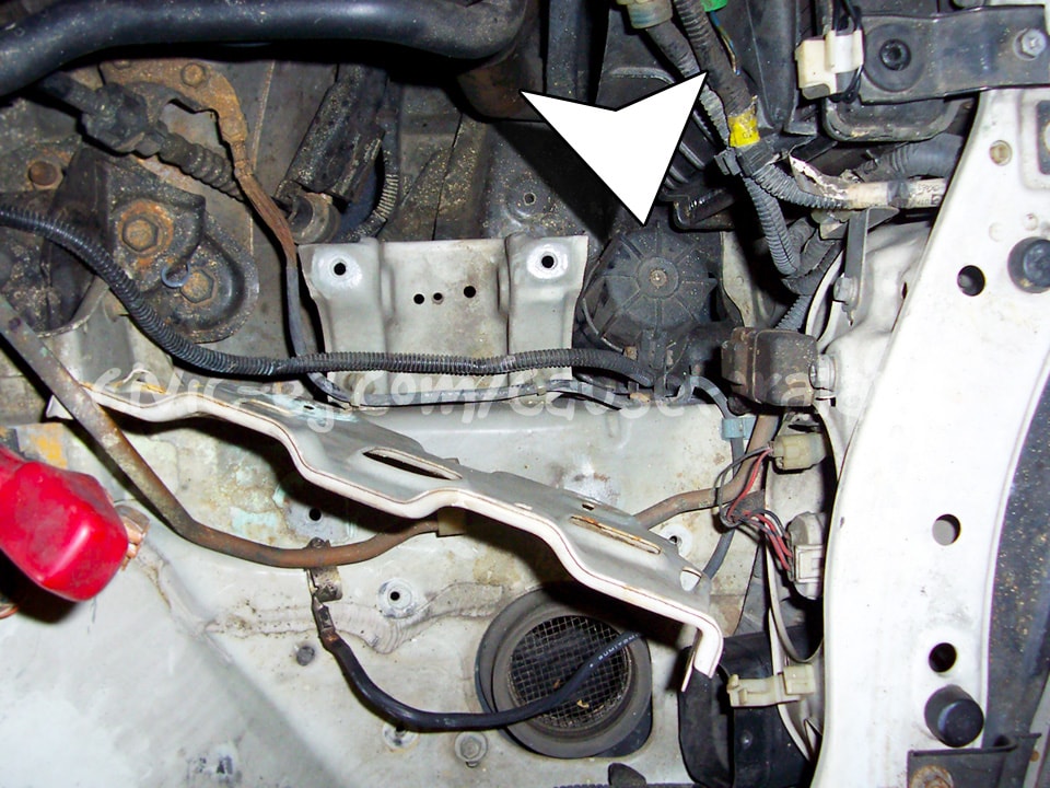
On the DA and many other cars, a great place to mount the engine bay siren is beneath the battery tray. Wrap the wires in some small diameter split loom and zip tie it alongside the factory wiring.


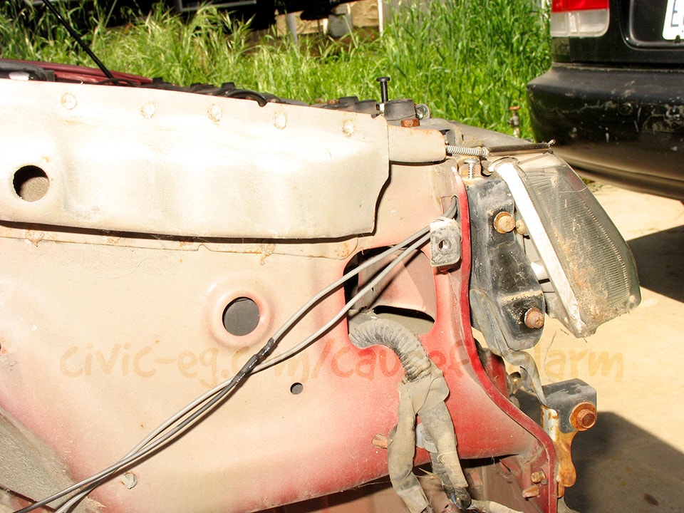
Beneath the fender is another great option, especially because it gives you a route for the hood pin wires.
Sensor (tilt)
The tilt sensor mounts with a single screw. The mounting location isn't critical, as long as it's parallel to the floorboard. Put a diode on the end of the trigger wire with the striped side facing the sensor. You'll need a diode on the other trigger that you're isolating, with the non-striped ends tied together and connected to the alarm side. Connect the tilt sensor's orange wire to the orange negative ground when-armed output on the alarm. Connect the red to constant 12v before the backup battery.
Sensor (glass breakage)
I usually mount the glass sensor module alongside the alarm control unit. Run the mic so that it's exposed to the open air of the cabin. Placement and orientation doesn't affect its performance as long as it's not sealed off in a seperate air space from the windows. The harness is plug and play.
Getting Serious
Remove Rear Seats
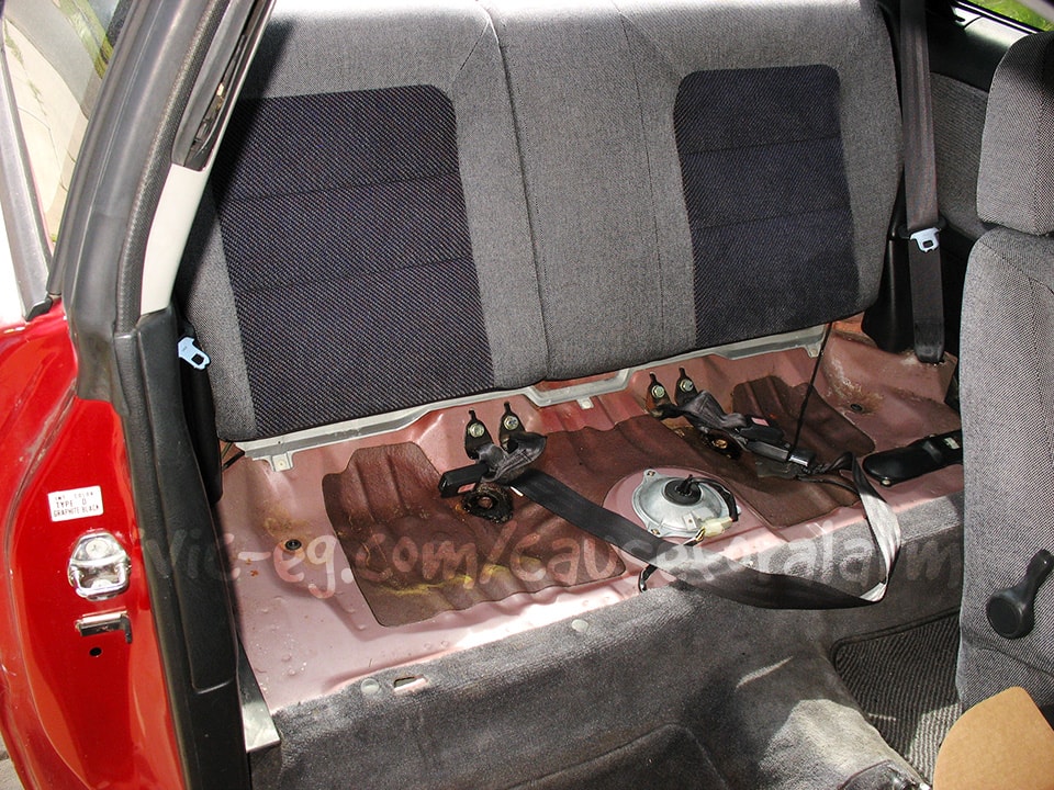
Now it's time to start taking apart your interior. The lower seat cushion is held in by one 10mm bolt in the center between the lower and upper seat cushion. Pull it up from the back and slide it out of the hooks in the front. Disconnect the rear seat backs at the outside edges first. Remove the rear passenger side seat back first so you can get to the 10mm in the middle.
Remove Rear Quarter Plastic

Track down and remove all the screws and work the rear quarter plastic out from behind the seatbelt.
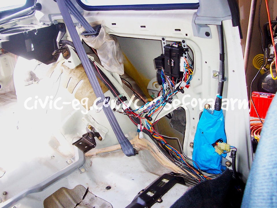
Mount the Control Unit
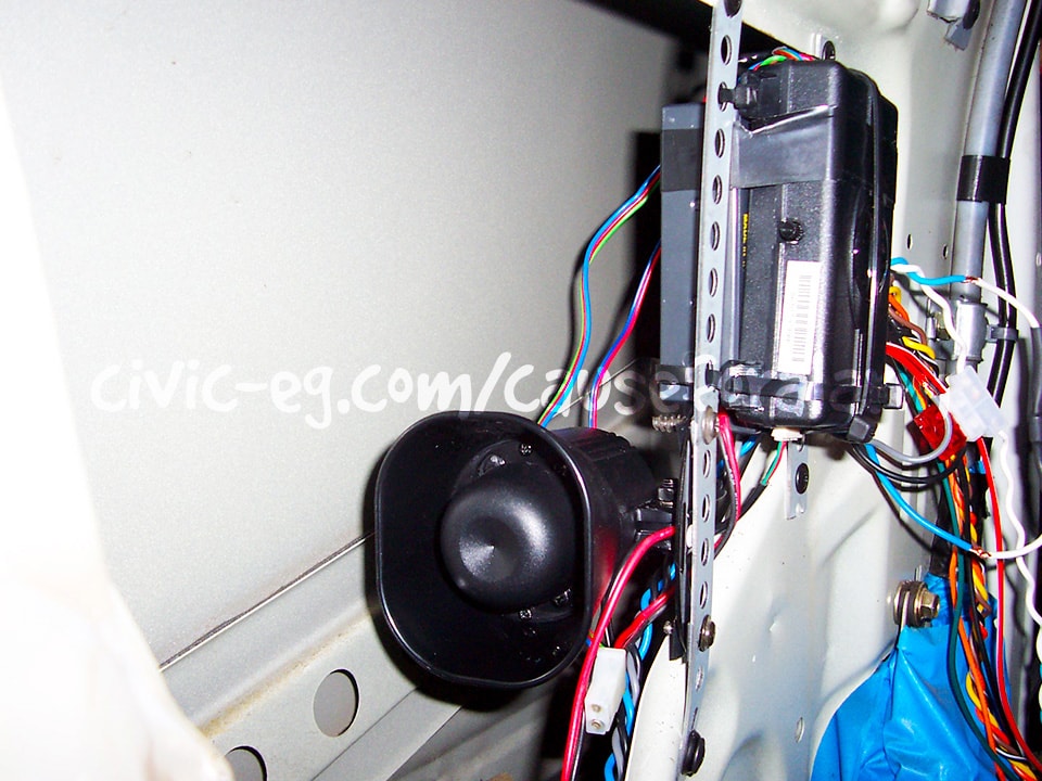
Tape and then zip tie the backup battery to the back of the control unit, and then secure it using backstraps, metal tapping screws, and zip ties.
Wiring
Piezo Siren
Find some place to mount the piezo next to the alarm brain. Point it downwards if you can so that moisture wont pool up inside. I'm using the siren that came with the alarm because this car already had a siren mounted in a good spot in the engine bay.
Tap into the brown and black/white wires that will be running to the siren under the hood. Put an inline fuse on between the brown wire and the engine bay siren's red wire. That way the thief can't short out your interior siren by cutting your engine bay siren's power wire and grounding it. Use a 1A fuse.
Grounds
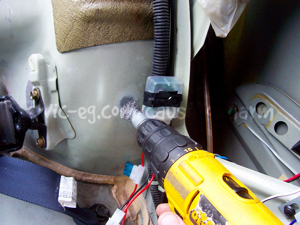

Group all the grounds together and crimp them all into one 8 gauge ring terminal. Choose a mounting point that is one continuous piece of sheet metal with the frame rails. Scrape the area down to the bare metal using a wire wheel, then mount the ring terminals using a star washer and a short metal tapping screw.
Door Trigger/Domelight
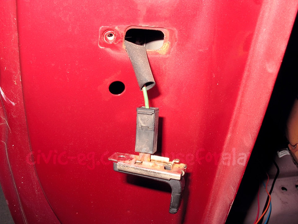
The door trigger wire runs along the base of the rear seat beneath the carpet. On Hondas/Acuras up to 00, you always want to tap into the passenger-side door trigger wire. Connect the alarm's green (negative door trigger input) to the light green/red (wire color varies with some cars). Honda/Acura door trigger wires have real thick insulation on them. Close all the doors, set your meter to continuity, connect one probe to chassis ground and the other to the suspected wire. There should be no continuity (meter shows 1). Open a door and the meter should drop to 0. Test each door individually.
Parking Lights, Trunk Trigger
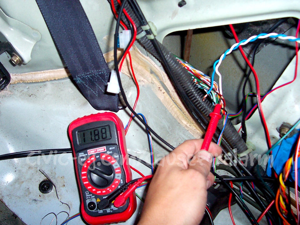
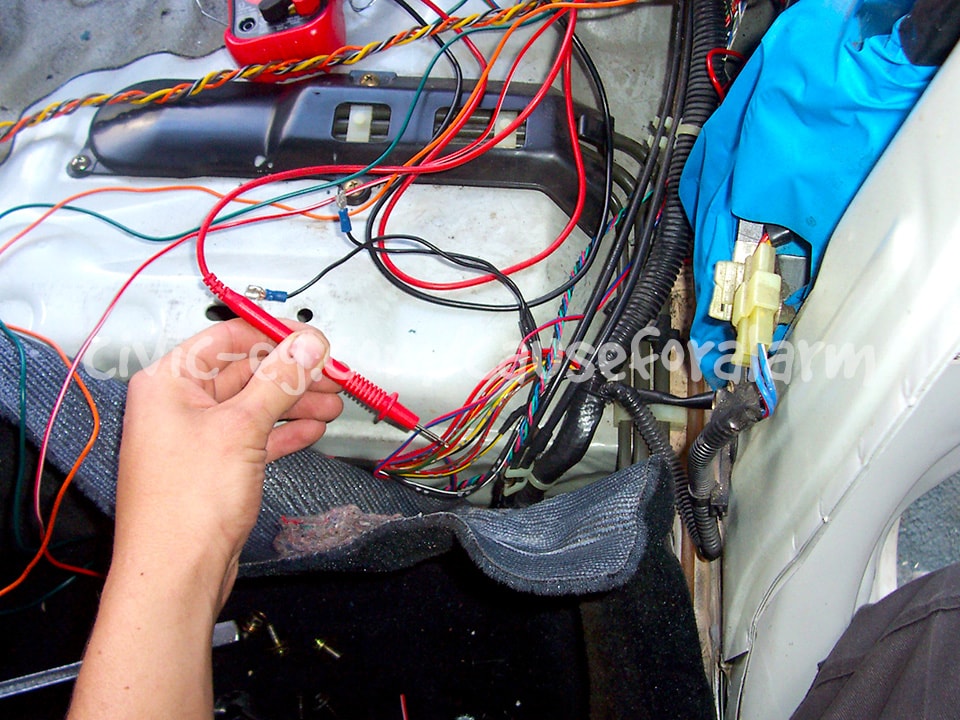
All of these wires can be found in the bundle going down the driver's side of the car to the rear. The parking light wire is red/blk with single dots. Verify this wire because there is a red/blk wire double dot that is not parking lights. The trunk trigger is green/black with a silver dot. Unfortunately there are several green/black wires in the same bundle, two have red dots, and two have silver dots. Test each of the silver dotted grn/blks with a multimeter. Set your meter to continuity. Ground the black probe and connect the red probe to the suspected wire. Pop the trunk. The correct wire will show continuity to ground when open, and infinite resistance with it shut.
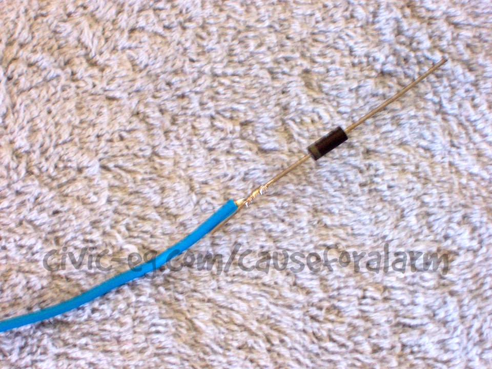
The alarm I'm installing has a trunk trigger input but no hood trigger input. I also have the battery backup trigger to contend with. The best thing to do is to tie them all into the alarm's blue negative trunk trigger input. You'll want them isolated because you don't want to have the trunk light on when the hood is open. Diodes have a stripe on the negative side. Twist the positive sides together and solder them to the alarm-side of the blue trunk trigger input. Then solder each trigger to its own diode on the striped ends. Make sure to tape over the entire diode when you're done. If you have an LCD two-way paging alarm, tie the backup battery and hood pin into the gray 22 gauge negative hood trigger input. There's no need to diode isolate them. If the battery is disconnected, the remote will tell you that your hood is open.
Start Kill
Low end DEI alarms come with an external relay. Cut the oem starter wire (black/white 10 gauge). Connect the relay's black 87 to the starter side of the starter wire. Connect the relay's green 30 to the key side. Connect the yellow wire to the car's black/yellow ignition wire. You can substitute any other start-kill circuit in place of the starter, ie clutch, neutral safety, or even the ignition.
High end DEI alarms give you three heavy gauge green/stripe wires. First, choose either normally open or normally closed. Normally open is more secure but if the alarm fails, you'll be stranded. Cut the start wire and connect the green/white wire to one end and the green wire to the other end. Cap off the green/black. You'll need to program the alarm option for normally open which is menu 2, option 11. If you want to do normally closed you'll use the green/white and green/black wires, then cap off the green wire. You wont have to change the programming.
Remote start alarms have a relay pack with 10 gauge green and purple wires for the start-kill/remote start. Remote start alarms complicate the stealth factor greatly. They require a bundle of 10 gauge wires to be connected to the ignition. Cut the car's black/white starter wire and connect purple to the starter side and green to the key side.
Stealth Start Kills
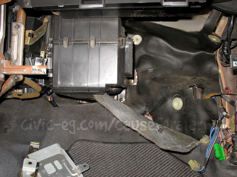
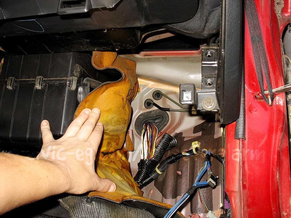
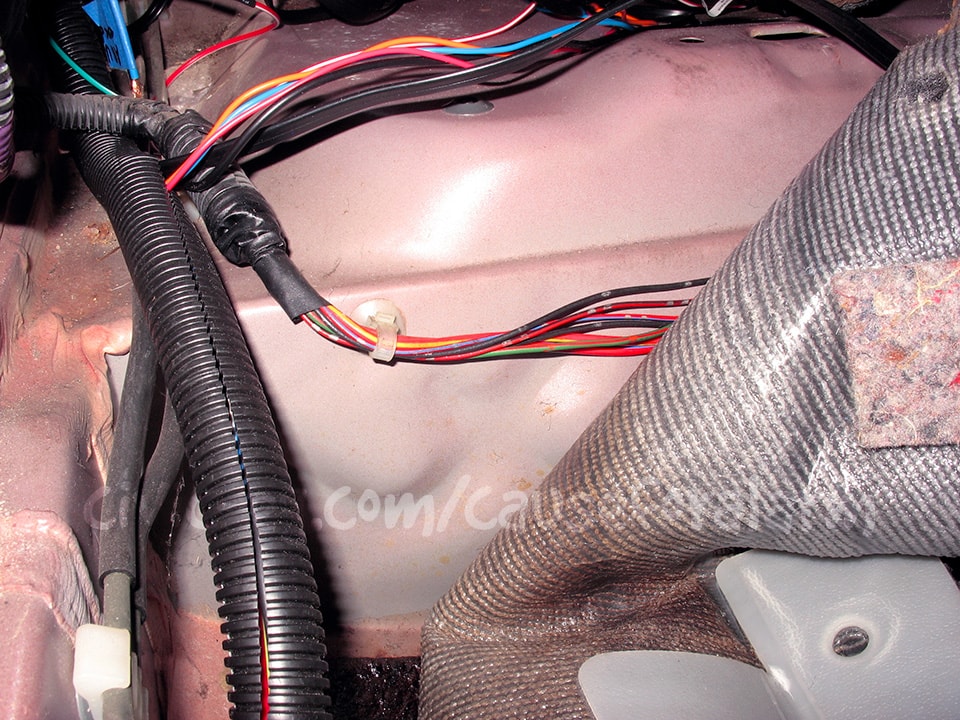
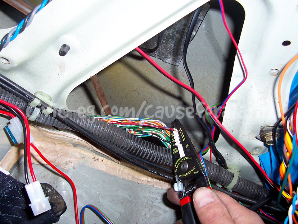
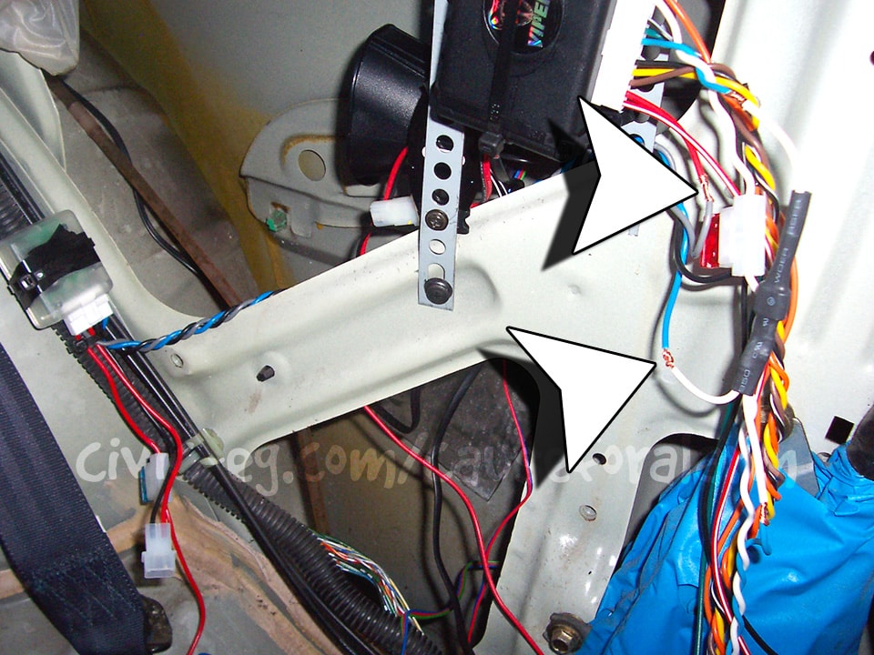
Rather than relying solely on killing the engine starter, you should get creative with the alarm start-kill, and you should use it in conjunction with a separate kill switch. For example, you could go to the engine harness under the firewall mat, and splice your start kill and kill switch wires on ECU outputs. Some examples of wires to interrupt would be the grn/yel Main Relay trigger wire. There are also a pair of yel/blk Main Relay power wires, and a pair of blk Main Relay ground wires. The 10 gauge blk/wht starter, blk/yel ignition, and wht Constant 12v wires all pass through this grommet in the firewall. Tapping into them here instead of under the driver's side dash is much more stealthy and makes it difficult to tamper with.

These zip mounts can easily be pried open and reused in order to tuck your alarm wires into OEM looms and bundles.
Backup Battery (DEI 520T)
Leave the module unplugged until the wiring is completed. Tap the blue trigger wire into the blue trunk trigger wire or the gray 22 gauge hood pin input on alarm's that have it. It's a good idea to isolate the triggers using a diode. The high end alarms come with the diodes in this white heat shrink. This alarm didn't, so good thing I have lots of them lying around.
The diagram that comes with the DEI 520T is great, but doesn't cover how it's tied in with this install's other power and ground connections, trunk and hood pin triggers. Please consult my Visual Guide to Car Alarm Installation available to Patreons at patreon.com/boyshit.
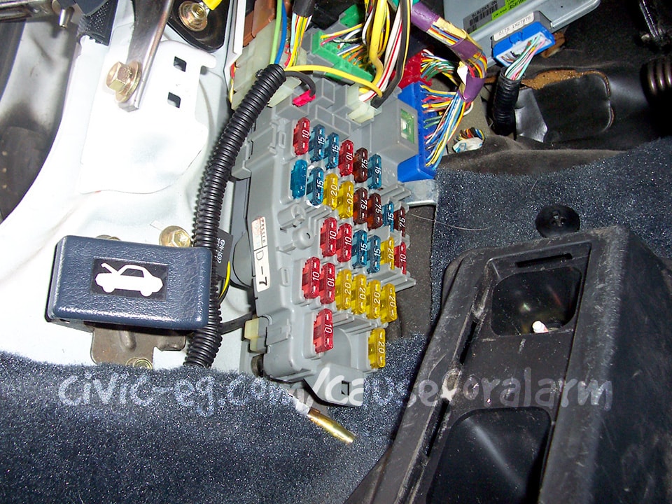
Under Dash Fusebox
Constant 12v, Ignition 12v, Parking Lights

A and C are Constant 12v, but C is preferable because there's nothing else on that circuit. It requires a fuse in #13 (use the same Amp rating as the alarm's constant input). B is Parking Lights, or you can connect the alarm to RED/BLK at various points in the car. D is Accessory 12v and E is Ignition 2 12v, which you might use if you install remote start. Connect the alarm's yellow Ignition 12v input to the 10 gauge BLK/YEL in the plug harness beside B. You can alternatively connect the alarm's red Constant 12v to the WHT wire here.
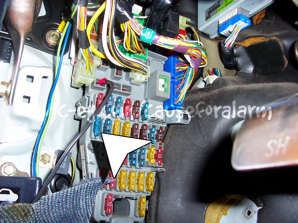
Crimp a female quick disconnect to your backup battery's extended Constant 12v input wire and connect it to fusebox output C. Some heat shrink over the female quick disconnect will make it look OEM. Put a fuse in the empty #13 slot.
Ignition 12V
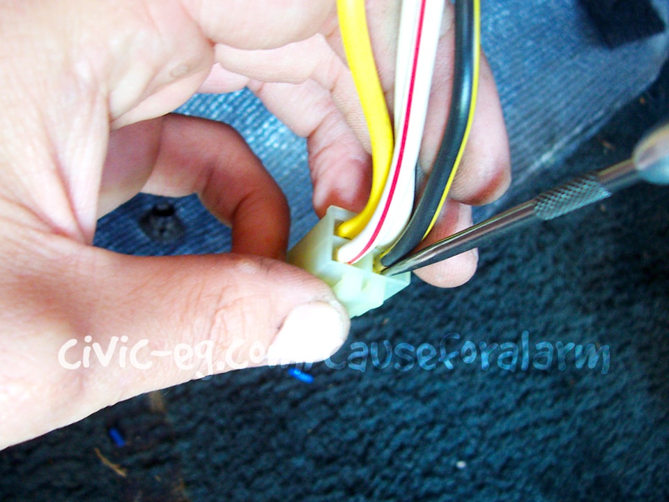
Use a straight pick to de-pin the black/yellow ignition wire.
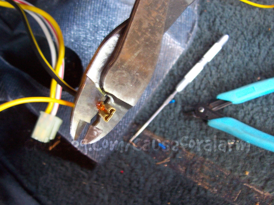
Use the pick to pry open the little crimps over the insulation. Then strip the insulation back just slightly and lay your alarm's extended ignition input wire against the OEM ignition wire. Crimp the little tabs down.
This was one of my earliest installs. Today I would tuck these wires away completely.
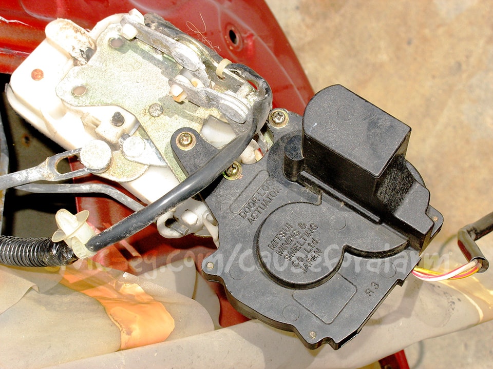
Door Locks
Power Door Locks
If your car has power door locks, you will want to hook up the keyless entry. If your car has manual locks, you can install aftermarket actuators (recommend 2 wire), convert to power door locks, or just not have keyless entry at all. The lock wire colors vary a lot between the years and models. On the DA, lock is green/white, unlock is green/red, and they can be found under the kickpanel. Some DEI alarms come with your choice of a 3 pin connector or the 6 wire 451M relay pack. You don't use the relay pack when you have factory door locks. Plug in the 3 pin connector and connect the green negative lock output (positive unlock) to the lock wire and the blue negative unlock output (positive lock) to the unlock wire.
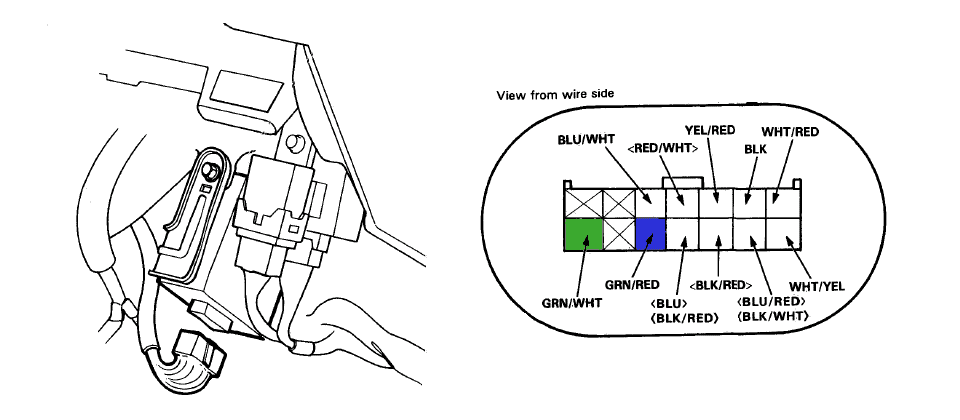
Some DEI alarms come with the 451M built into the alarm brain and a 7 pin harness for the door locks. In that case, wire it up as follows (de-pin the wires marked in red):
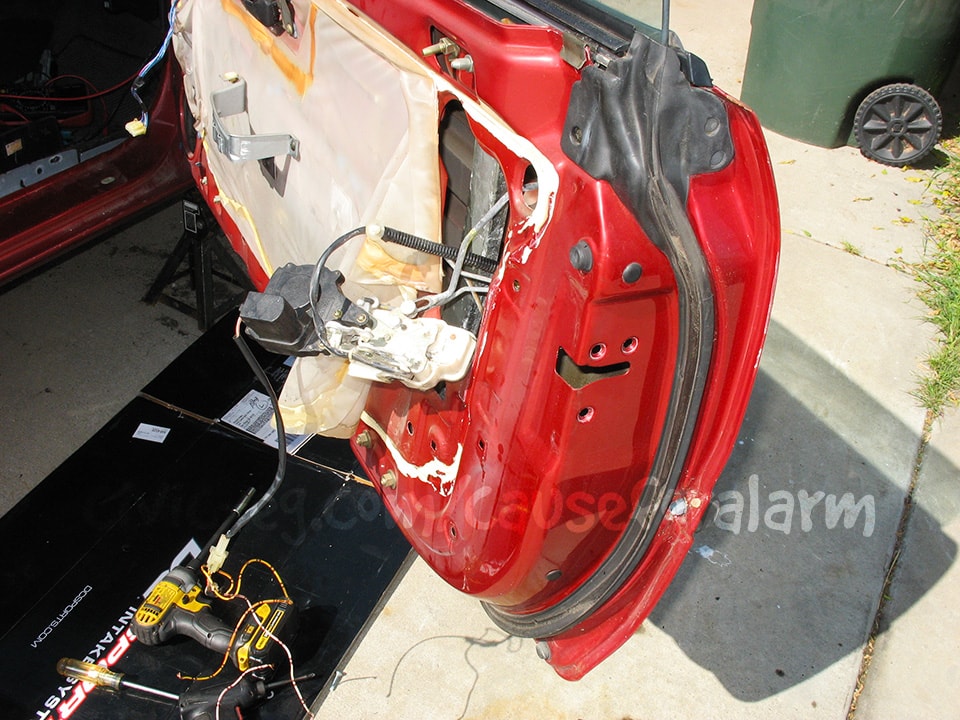
Adding Doorlock Actuators
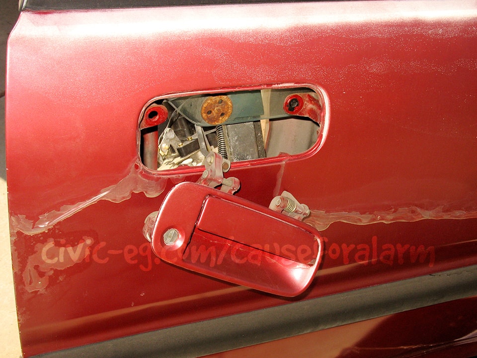
If your car has manual locks, I strongly recommend adding OEM actuators to the doors. Keyless entry is a game-changing feature. It also prevents you from accidentally setting off the alarm when you open the doors with the key, because you will be using the key fob to unlock the doors instead.
EF and DA doorlock actuators will mount right up to your manual lock door latches. They are attached with three very small phillips screws, that strip very easily. Use a T handle screw driver to avoid stripping, and have a small set of locking pliers as backup. Don't forget to get both sides of the wire harness and as much length of wire as possible. OEM actuators are different on the driver and passenger sides, being mirror images of each other, but rear actuators can be used on front doors and vice versa.
On OEM Honda doorlock actuators, yel/red (-), wht/red (+) is lock, while reversing the polarity to yel/red (+), wht/red (-) is unlock.
Please consult my Visual Guide to Car Alarm Installation available to Patreons at patreon.com/boyshit. There I cover all the different combinations of wiring doorlocks in great detail. Additionally there are diagrams of wiring actuators as well as start kills, trunk popper, battery backup, additional sensors specifically to Hondas and Acuras.
Trunk Pop
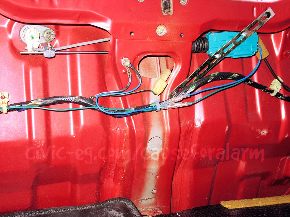
Use backstraps, speed clips, and metal tapping screws to secure the actuator without piercing through to the outside.
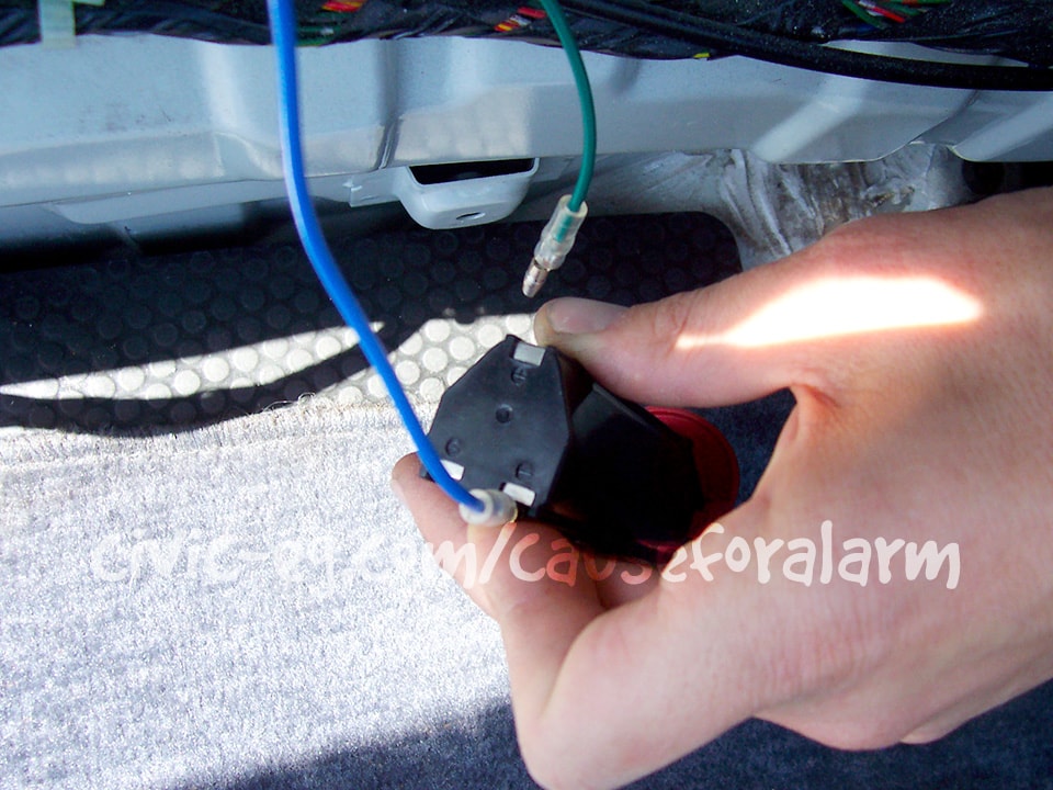
Here I'm using my drill battery to test positive and negative on the actuator wires to determine which side to ground and which to connect to the relay output.
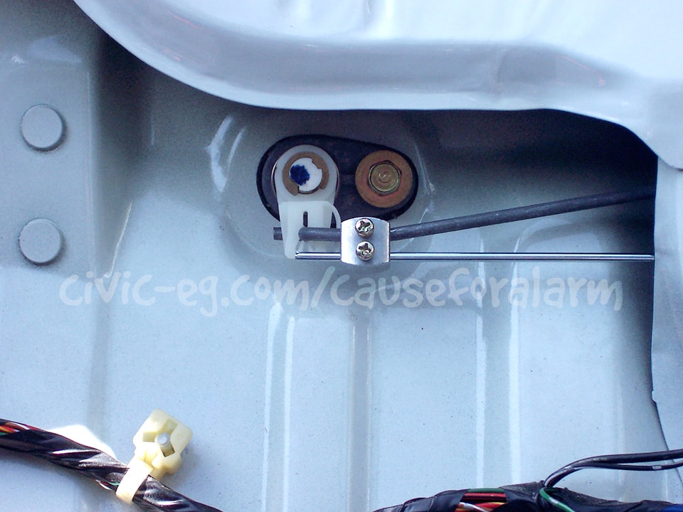
The length of this bar should center the actuator in it's travel. Use thread locker on these little screws.
Program the Alarm Settings
Driver's Priority Unlock
If you've wired the doorlocks for Driver's Priority Unlock, you'll have to program the "2nd Unlock" output on the wht/blu wire before this will work properly.
Valet Mode
By default it takes one press on the valet with the ignition on to put the alarm in valet. Program it for 2 or more presses and write it down in the booklet, or just program whatever options you want and then remove the valet button altogether.
Once you are satisfied that the alarm is fully functional, put your interior back together and give it one more quick test.
Testing the Alarm
Close the doors and trunk and arm the alarm. Make sure both doors lock when armed, unlock when disarmed. Also make sure the parking lights and LED flash. Make sure both sirens chirp. Unlock the door with the key and make sure it triggers the alarm, then test the other door and the trunk. Make sure the car wont start when the alarm is going off, but will start when it's disarmed. Try putting the alarm in valet mode and taking it out (turn the key on but the engine off and tap the valet button).
Finished Install
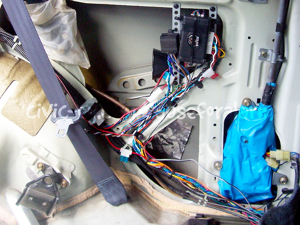
Here is an example of an alarm and components mounted with backstraps, electric tape, and zip ties.
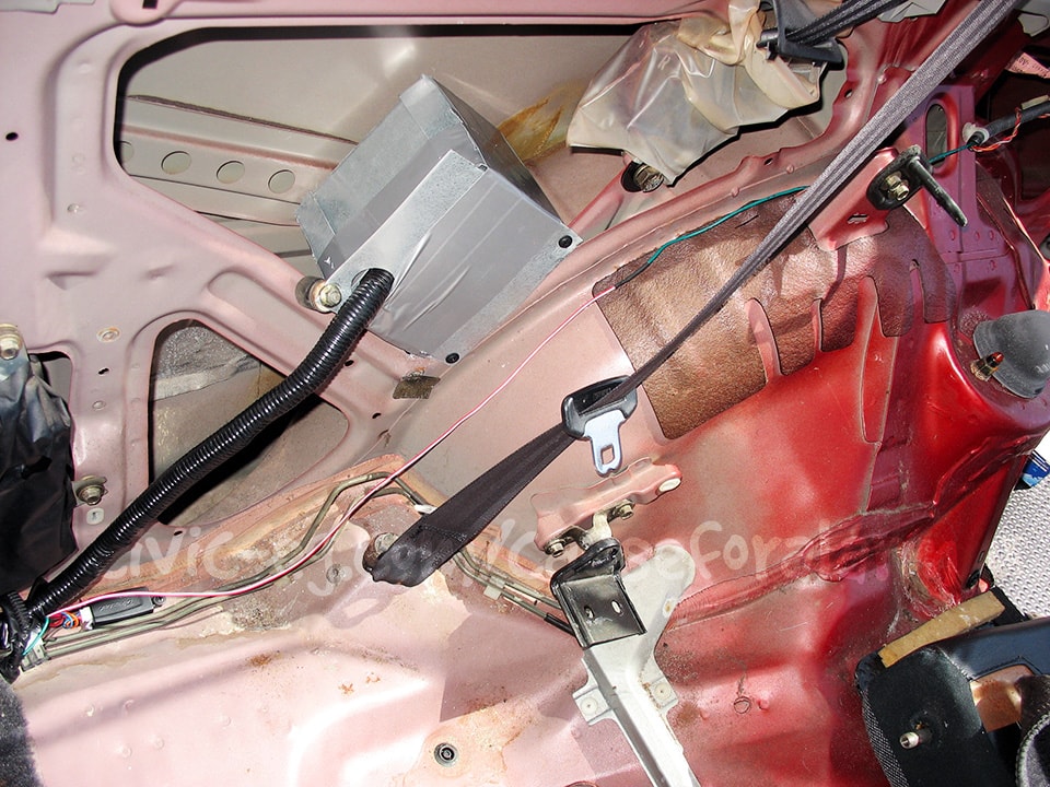
Here is a more current example of my work, where I roughly construct a sheet metal box to contain the alarm and components. This isn't meant to be a vault or an object of beauty, just a self-contained mounting solution that provides some protection to impact and moisture (cardboard lining). Rarely to be seen again once the interior has been reassembled.