
F23 Swap Guide
Out Now!
Stealth Car Alarm Install
1994-2001 Acura Integra
Alarm Bench Prep
The standard type of alarm install you get when you pay a professional to install your alarm just isn't effective. In order for an alarm to be effective, the control unit must be invisible and undetectable, the siren must be hidden and inaccessible, all wiring should be concealed in split loom, the alarm should have its own backup battery, and the alarm must be able to detect all types of intrusion.
OEM Wire Colors
| 1994-01 Acura Integra | ||
|---|---|---|
| WIRE | COLOR | LOCATION |
| 12 VOLT CONSTANT | FAR LEFT OPTION OUTPUT ON FUSE BLOCK | |
| STARTER | BLACK/WHITE | MAIN RELAY |
| IGNITION | BLACK/YELLOW | UNDER DASH FUSE BOX |
| PARKING LIGHTS (+) | RED/BLACK | REAR QUARTER HARNESS |
| TRUNK TRIGGER (-) | GREEN | REAR QUARTER HARNESS |
| DOOR TRIGGER (-) | LIGHT GREEN/RED | DRIVER'S RUNNING BOARD |
| POWER LOCK (-) | BLACK/WHITE | DRIVER'S KICK |
| POWER UNLOCK (-) | BLACK/RED | DRIVER'S KICK |
Choose a Location
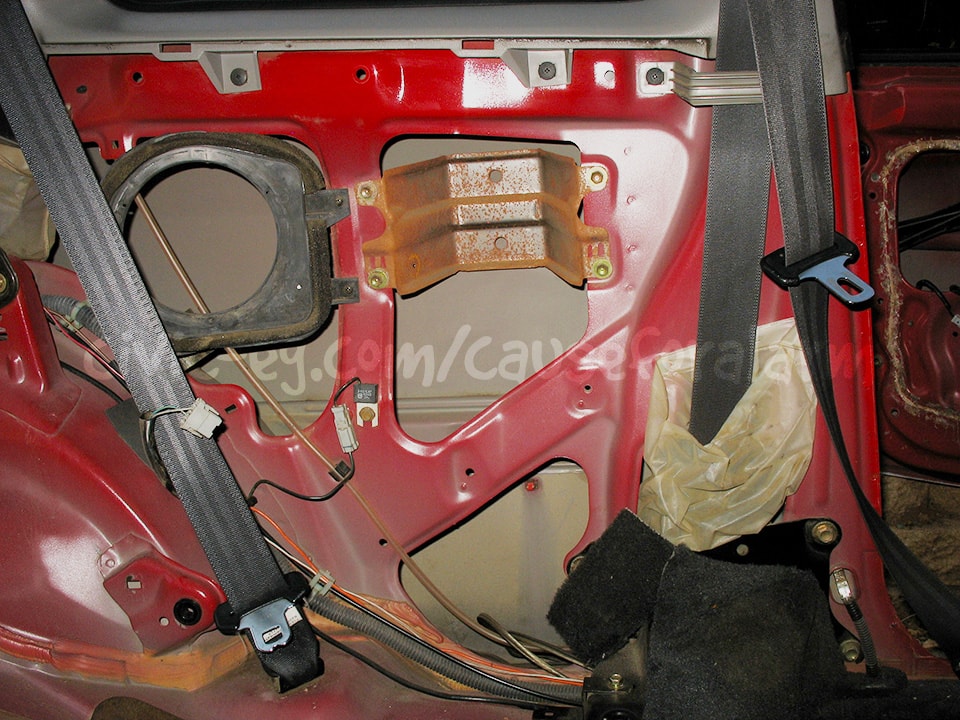
Rear Quarter Panel
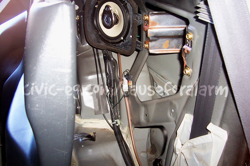
Alarm Peripherals
The best way to start the install is to get all of the alarm's peripherals out of the way. By peripherals I mean both sirens, the antenna, the valet button and LED, all the sensors including the hood pin, and mount the backup battery.
Antenna
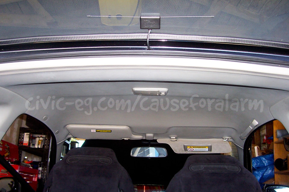
This is a difficult spot to mount the antenna and you'll have to take extra care adding "monkey snot" to seal up the grommets from moisture. It looks good, but a windshield or quarter glass install would be a lot easier.
Range is critical for two-way paging alarms. For the best possible range, mount the antenna up high and tuck any excess length loosely in the headliner. Never tightly bundle up the wire or range will suffer. Another aspect of antenna range is the strength of the power and ground connections. I'll go over that later.
LED
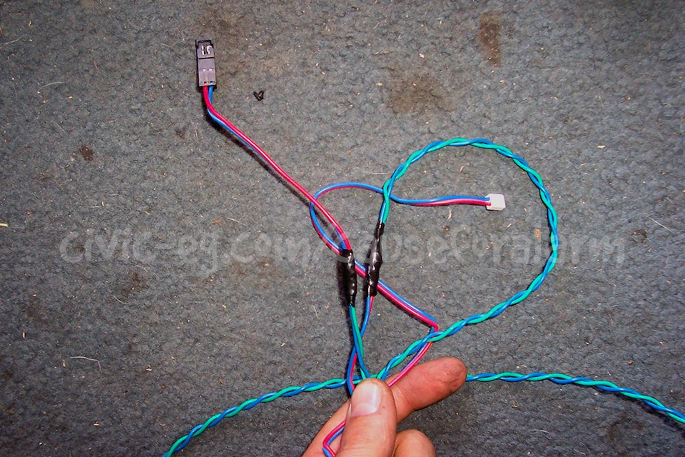
You'll often have to extend LED wires in rear quarter panel installs, unless you get an alarm that has the LED and Valet integrated into the antenna. In this case, I was reusing the LED from his old alarm.
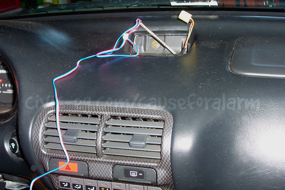
Clearance is very limited in the clock panel. Make sure the LED will fit before drilling a hole. Drill a hole using a 17/64 or 1/4 bit. The manual says 9/32, but then the LED will be loose so use the next size smaller and a round file. Press the LED in on a soft surface like a carpeted work bench.
Valet Button
You can mount the valet button the same as you would an LED, except you want to hide it. I usually just wait until the install is finished, program whatever options I want, and then remove the valet button. You can put the alarm into valet by hitting lock, unlock, lock quickly in sequence on the remote.
Hood Pin
Siren
Tilt Sensor, Glass Break Sensor
This install only had one sensor and I didn't take any pictures. Just look through all the other write-ups. Between them I've covered every useful kind of sensor.
Getting Serious
Removing Lower Dash
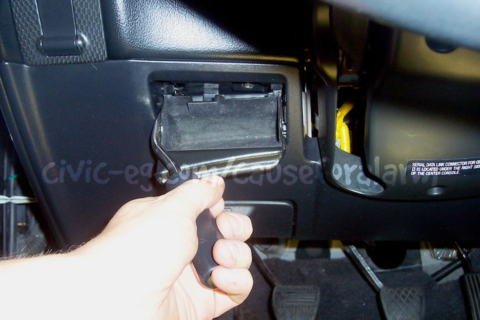
There's a screw hidden behind the coin pocket. Pry it out carefully as shown.

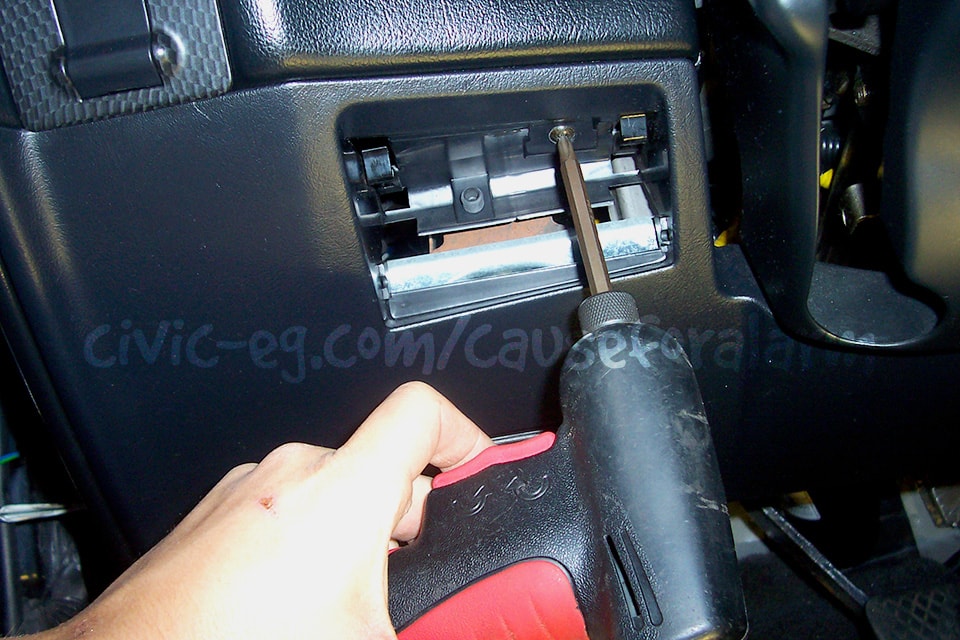
Remove the other screws and pop the lower dash panel off starting at the top.
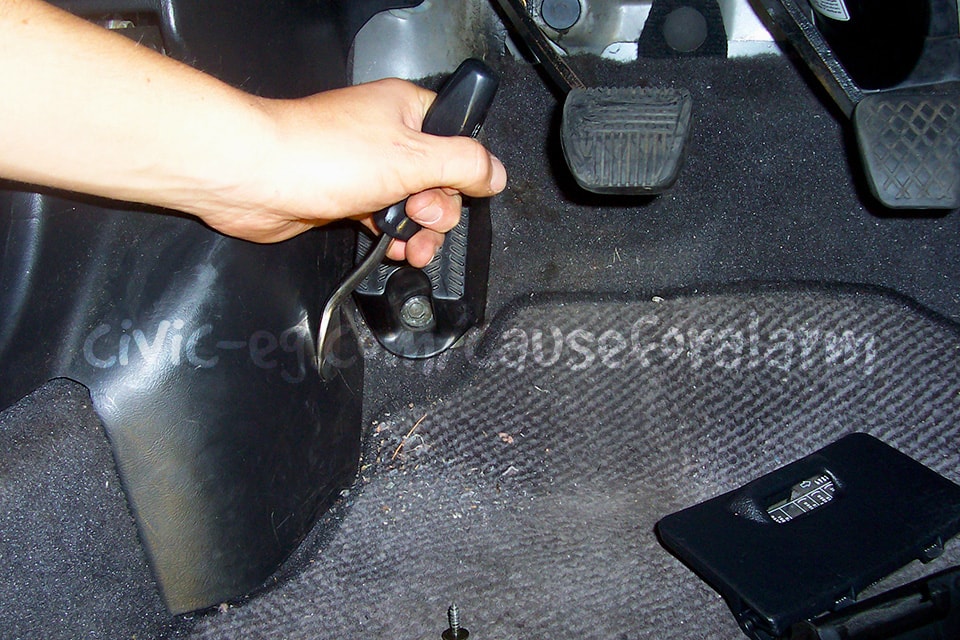
Use the panel popper to remove the stubborn pop in the driver's kick.
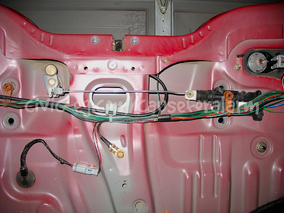
Removing Rear Quarter Plastic

Remove the plastic stops at the far edges of the rear seat-backs, then push a seat-back to the center and remove the seat pivot collar that is between the side of the seat and the quarter plastic. Fold them over and out of the way without crushing the rear carpet. Remove the 10mm at the back of the seat-bottom, then lift up the back and unhook the front two clips.
Remove enough of the screws and bolts so that you can pry the rear quarter out enough to work behind. If this is your first or only install, you may just pull the whole plastic out.
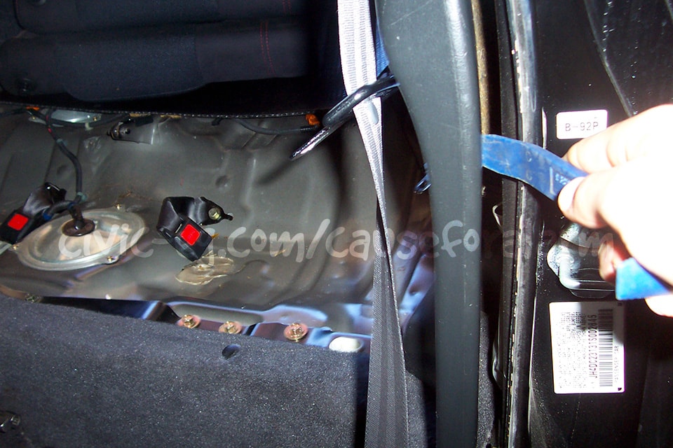
Carefully pry the edge off as shown. Try not to kill your fingers or crease the plastic.
This is where the magic happens. Honestly, just remove the whole rear quarter panel cover.
Mount the Control Unit
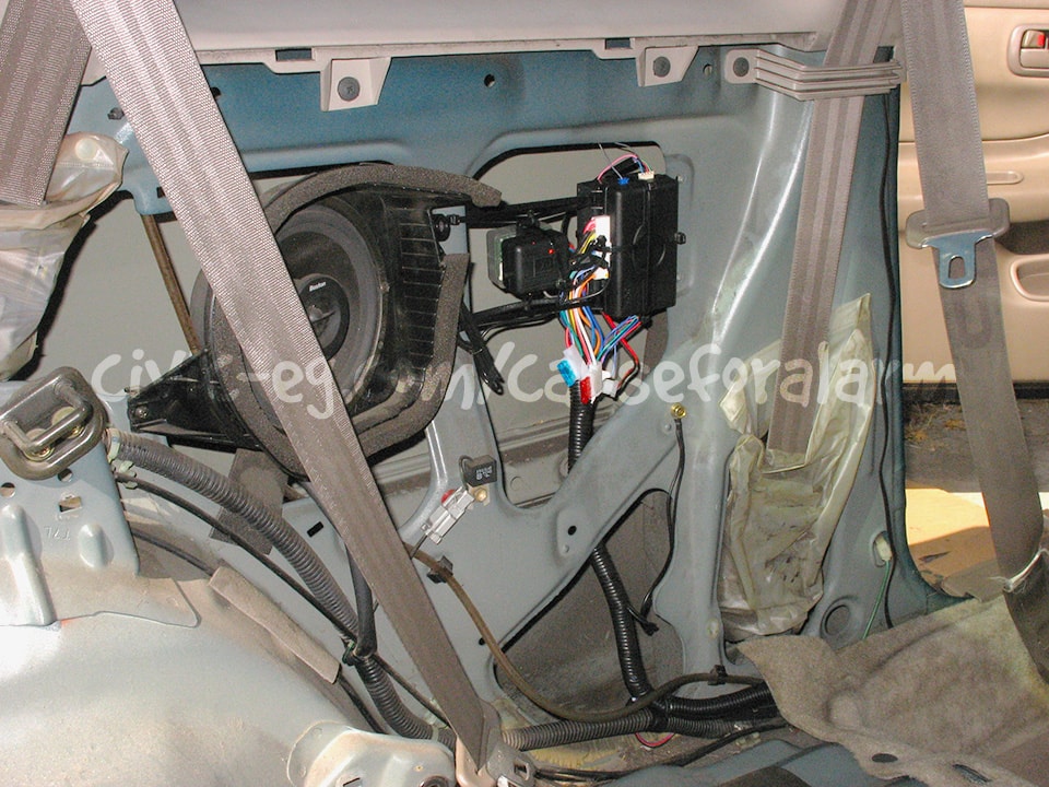
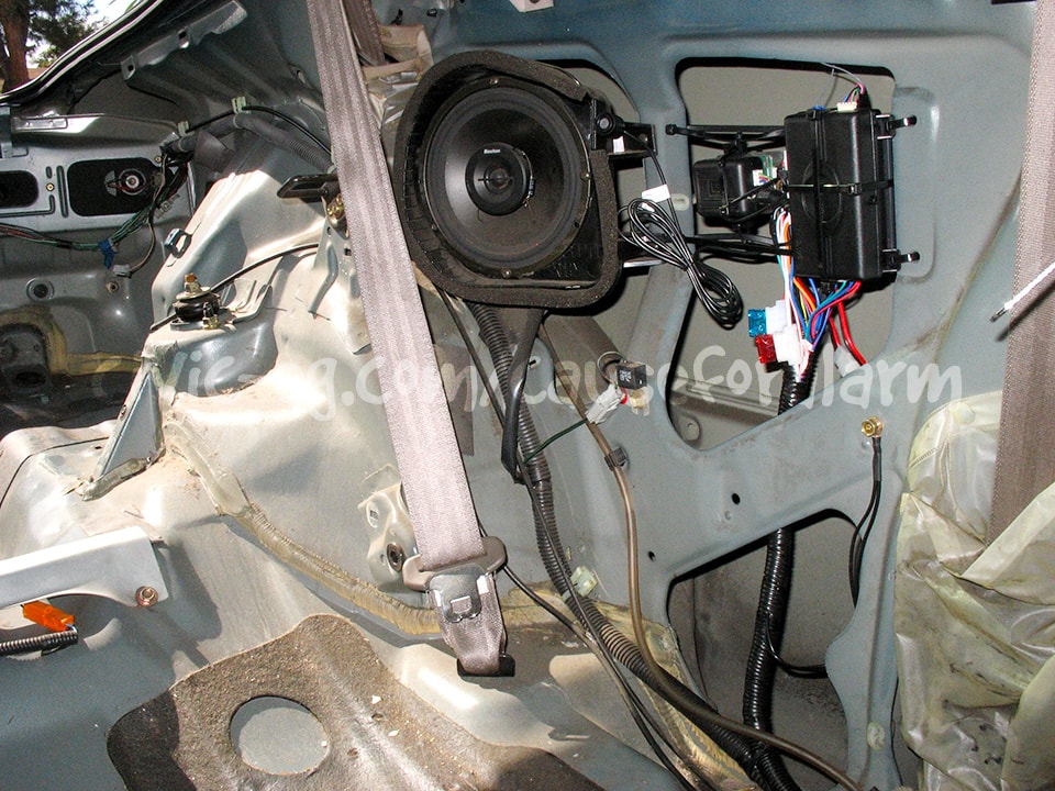
These pics are from the old way I used to install alarms. If you follow my Alarm Prep Guide, you'll be mounting an alarm in a box here instead.
Wiring
Piezo Siren
Tap into the brown and black/white wires that will be running to the siren under the hood. Put an inline fuse on between the brown wire and the engine bay siren's red wire. That way the thief can't short out your interior siren by cutting your engine bay siren's power wire and grounding it. Use a 1A fuse. If you have power door locks and scavenged the 451M module as I mentioned in Alarm Prep, you can use the purple wires and fuse holder for the sirens. This can be very useful for branching the sirens cleanly. You connect the single wire to the engine bay siren. Either of the wires on the other end of the fuse connects to the alarm's brown siren output, and the remaining wire connects to the piezo's power wire.
Grounds
Crimp all the ground wires into a single ring terminal, then ground it to the chassis on a factory bolt or a metal tapping screw with a lock washer. Scrape away any paint if necessary, then seal it again.
Door Trigger/Domelight
Close all the doors, set your meter to continuity, connect one probe to chassis ground and the other to the suspected wire. There should be no continuity (meter shows 1). Open a door and the meter should drop to 0. Test each door individually.
Trunk Trigger
The trunk trigger is one of the more difficult wires to locate and confirm, simply because there are many wires that are the same color. The trunk trigger is usually a 18 gauge green wire on this model. Scrape back some insulation and connect one of the probes from your meter. Set the meter to continuity. Ground the other probe. Have a friend pop the trunk manually (and close it again if it's the wrong wire). Your meter should show perfect continuity. This wire often gives me problems. You can confirm the wire color by going to the latch. There will be a pin with a single wire that is very obviously for the trunk trigger.
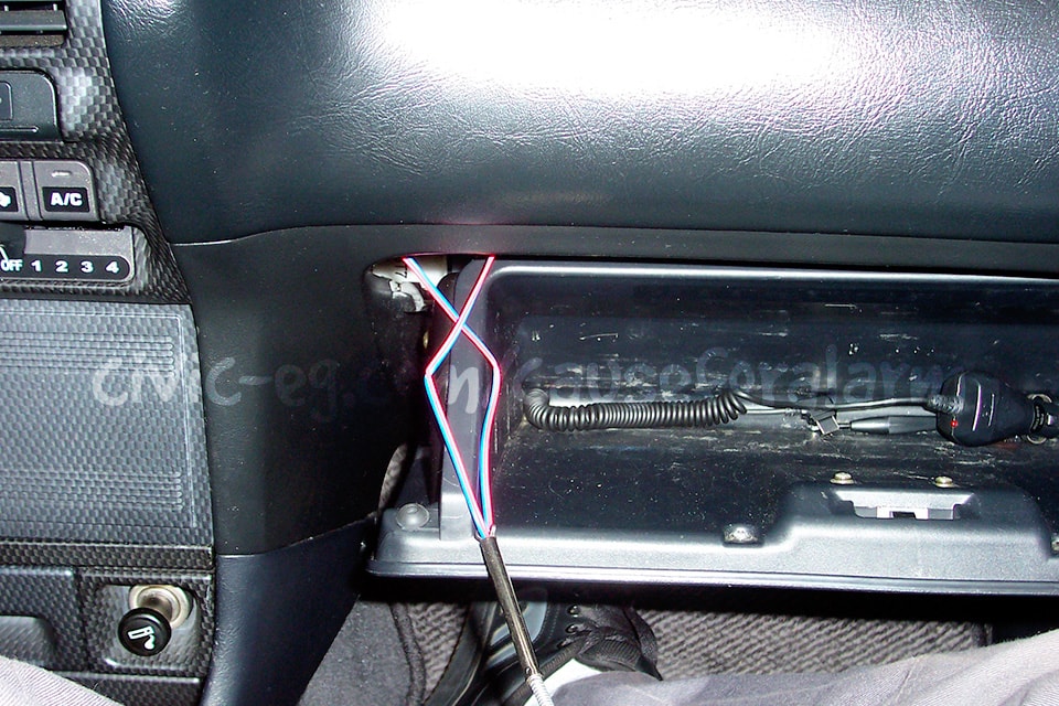
Run Wires To Dash
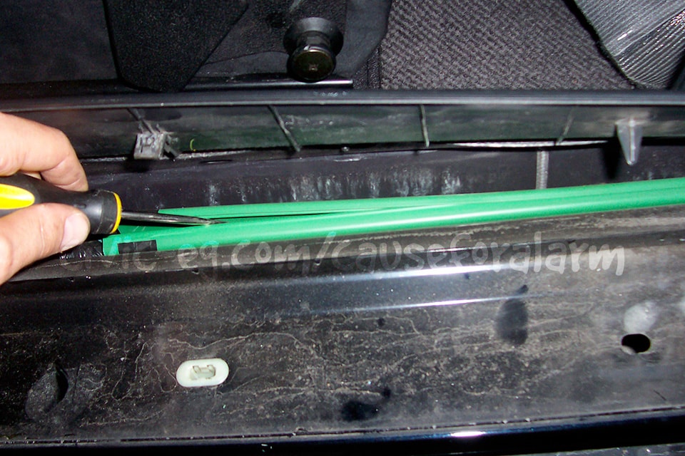
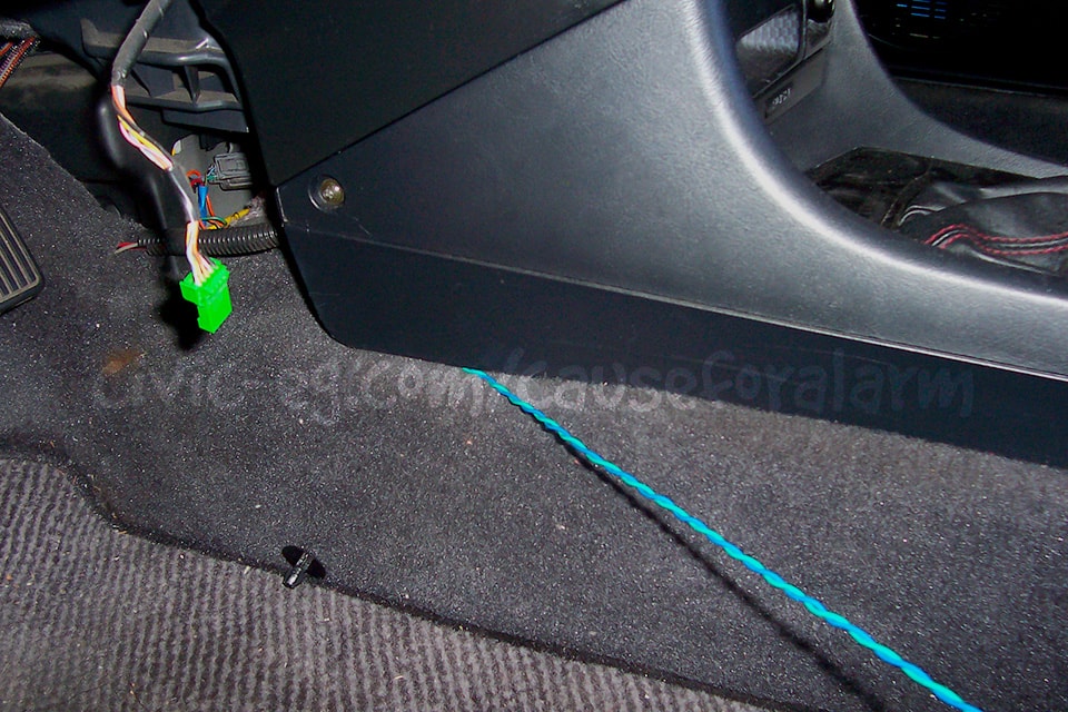
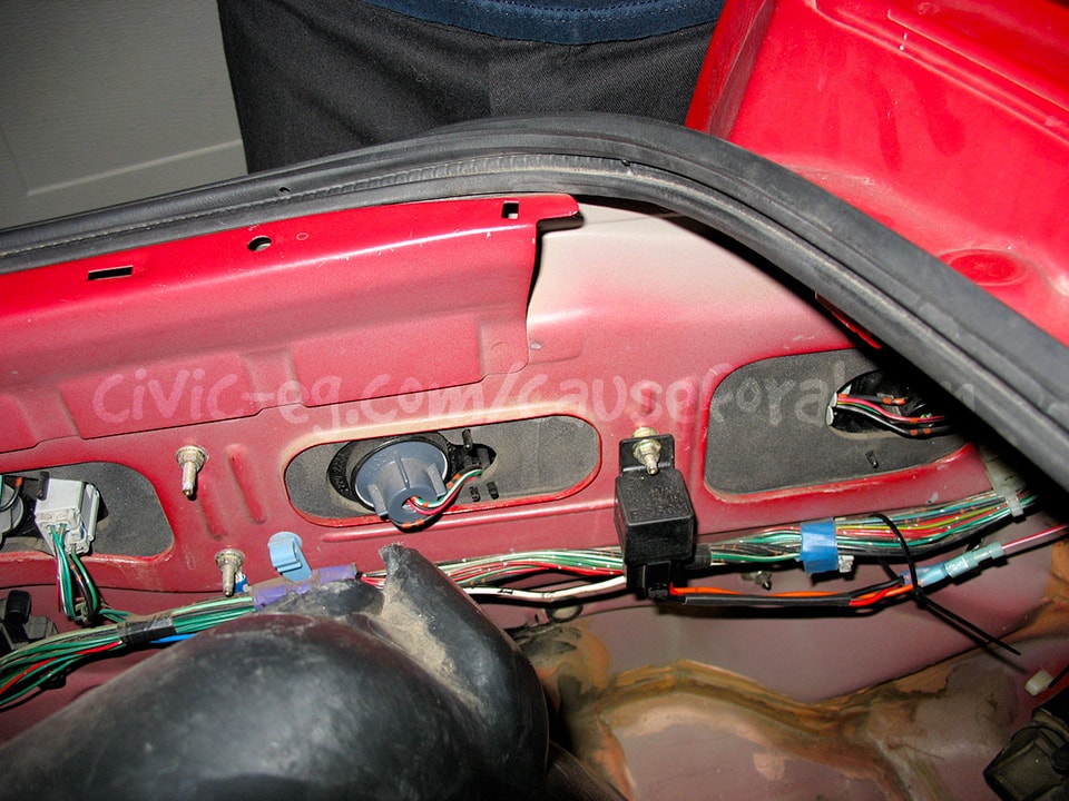
Pry open these plastic holders in the running board so that you can run all your alarm wires inside. Use split loom for the sections between the plastic holders. Basically you'll need to run your door lock wires, ignition wire, constant wire, and the ground-when-armed wire if you are doing a second start-kill.
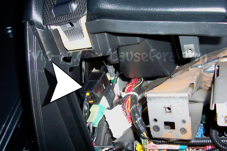
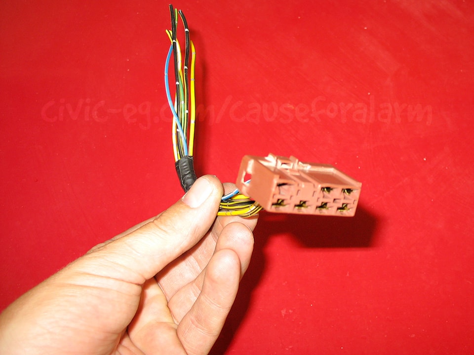
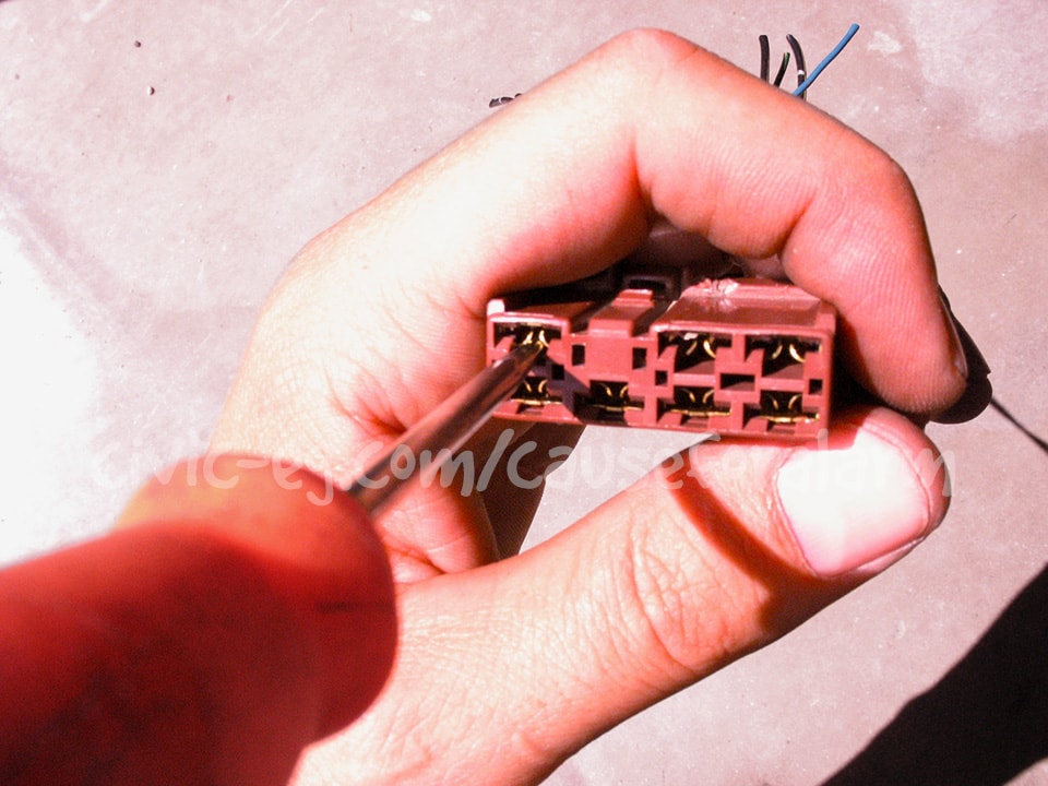
Fuse Box Option Outputs
This model Integra, like many other Hondas/Acuras, has extra option power outputs on the under-dash fuse box. You can source option plugs in the doors and engine bays at the junkyard, or you can use female quick disconnects. There are constant 12v outputs, accessory 12v outputs, and a parking light output.
94-95 Integra Fuse Box
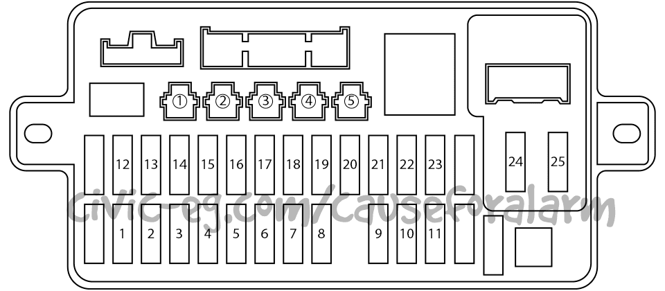
#1 and #2 option outputs are Constant 12v (insert a fuse into #17 for option #1), #3 and #5 are Accessory 12v (insert a fuse into #16 for option #3), and #4 is Parking Lights (fuse 19).
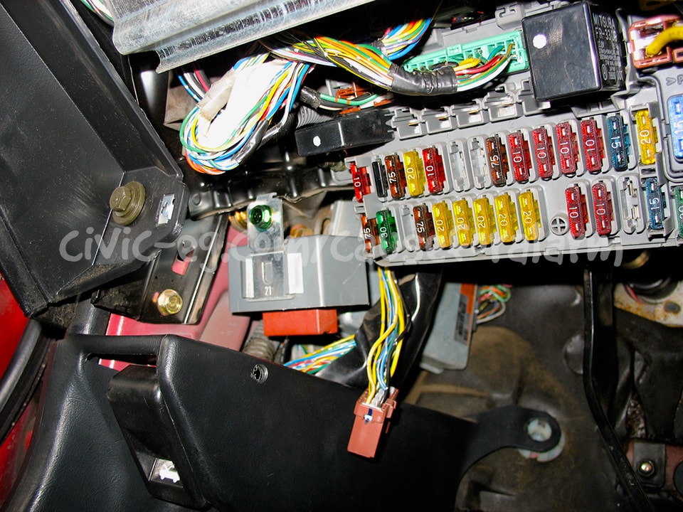
96-01 Integra Fuse Box
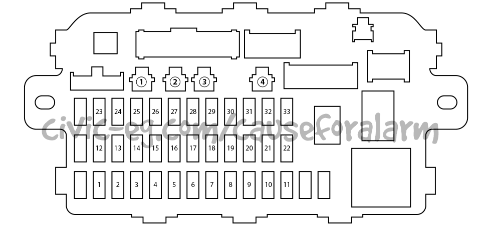
The option output #1 on the under dash fuse box is a constant 12v. Use an option plug connector and an inline fuse holder. When the alarm install is finished, insert a fuse with the same rating as the one on the alarm's Constant 12v input.
Parking Lights
You can connect the alarm to the parking lights at the fuse box option output or at the RED/BLK wire in the running boards.
Constant 12V
96-01 Integra Fuse Box
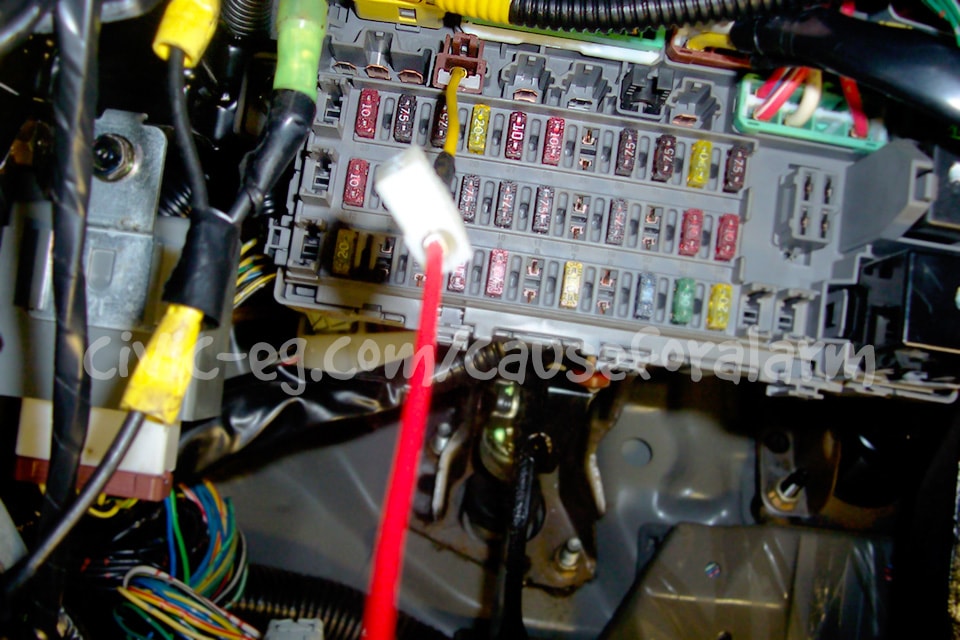
The large sloppy crimp connector work to the left was not my doing.
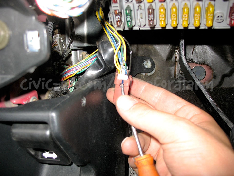
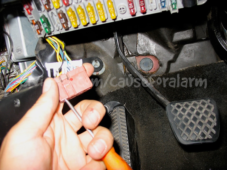
Ignition 12V
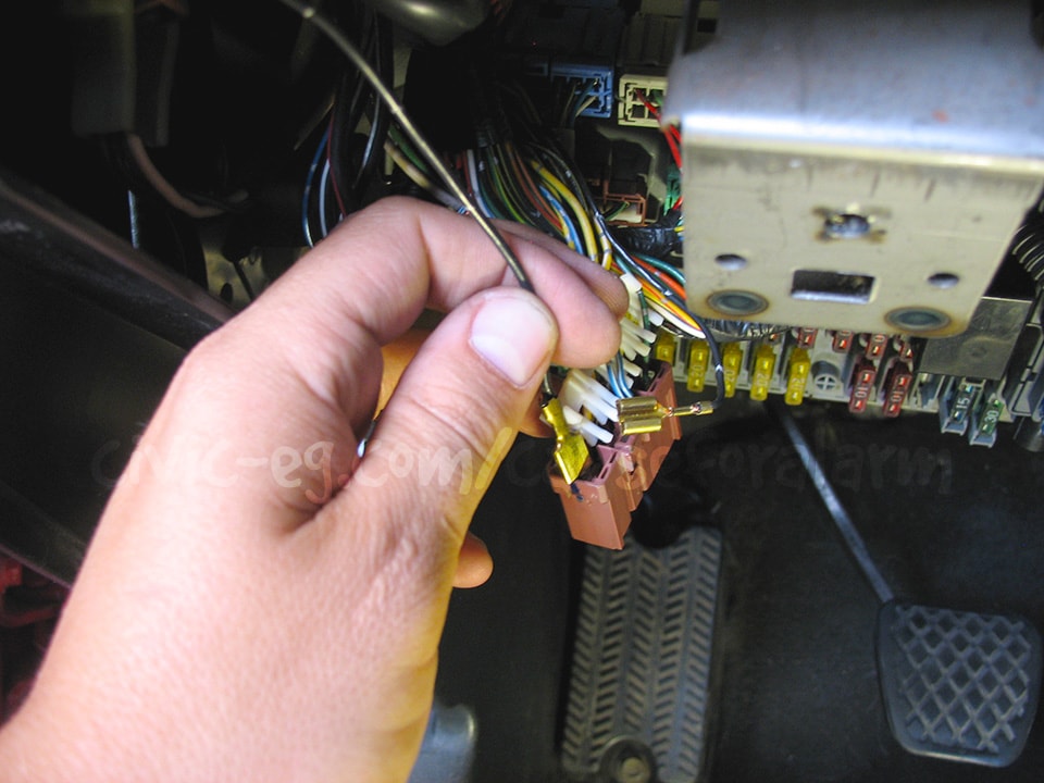
You can get a true Ignition 12v from the 10 gauge black/yellow wire at the under-dash fuse box or the ignition harness. The stealthiest way of tapping into it is to de-pin the wire at the plug connector, pry open the pin, crimp and solder your wire to the ignition wire, then re-pin it.
Start Kills
Starter Relay
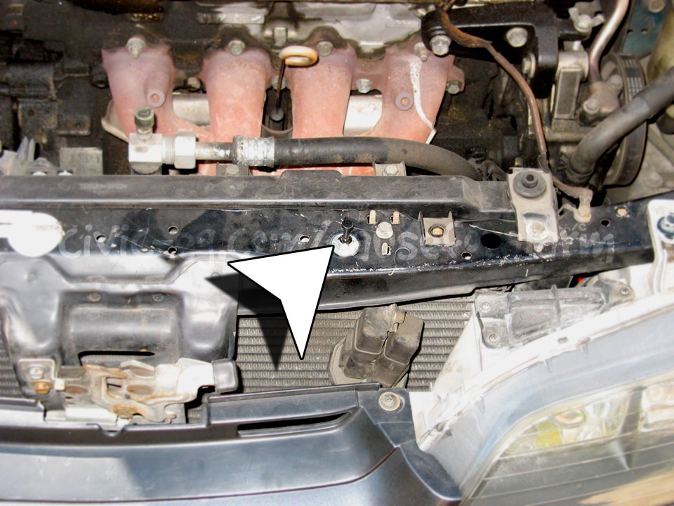
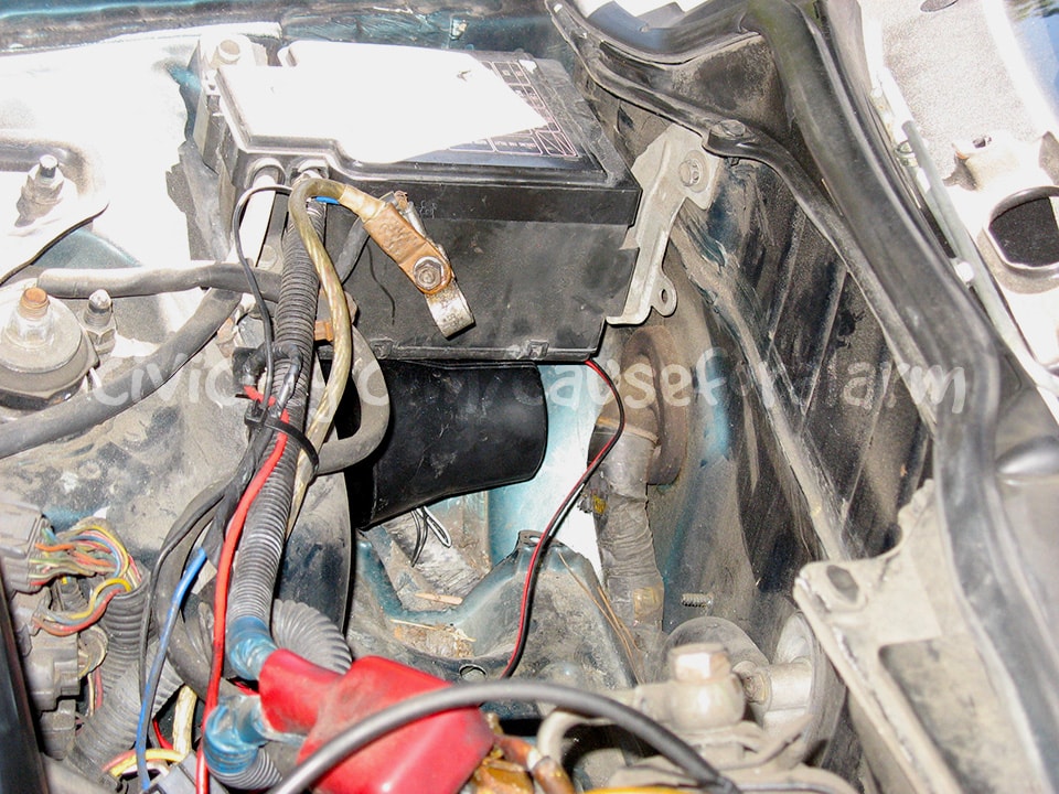
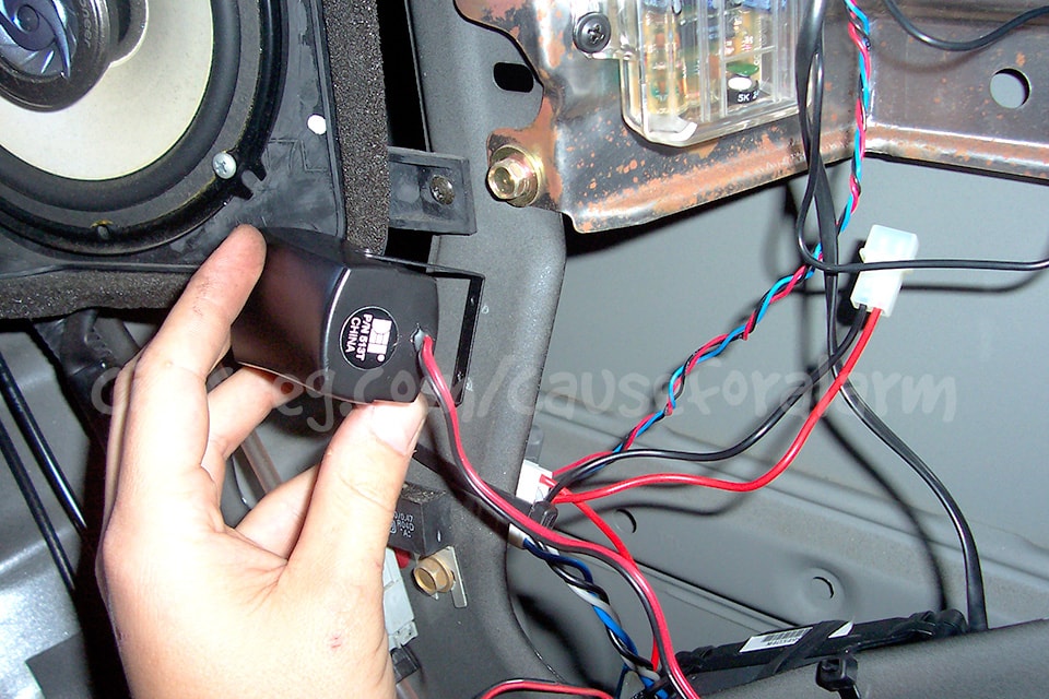
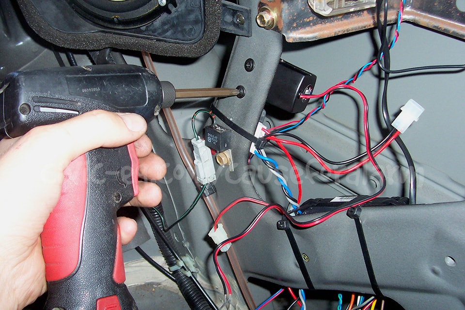
In this example I put the alarm's start-kill relay near the oem starter relay where I interrupted the BLK/WHT wire. I used a factory threaded hole to hold the relay in place. This start-kill should never be relied on by itself. I use it as a secondary measure to misdirect the thief and make the no-start condition harder to diagnose. If they manage to find the relay where I've hidden it, they will be suprised by the second start-kill. If this is not enough to make them give up, it's only because they have your car completely secluded and in that case, there is little that can save your car besides a tracking device.
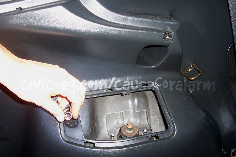
Main Relay Start Kill
This part is optional but I like to get a main relay harness from the junkyard. I de-pin the ground wire to use in place of my original ground pin. I tuck that one away and leave it intact and wire the junkyard ground to a switch or a start kill relay to the alarm.
I also like to get an extra main relay and cut off a harness to make a dummy in the original location. You can even splice the GRN/YEL and BLK to the real wires so that it clicks just like the real relay.
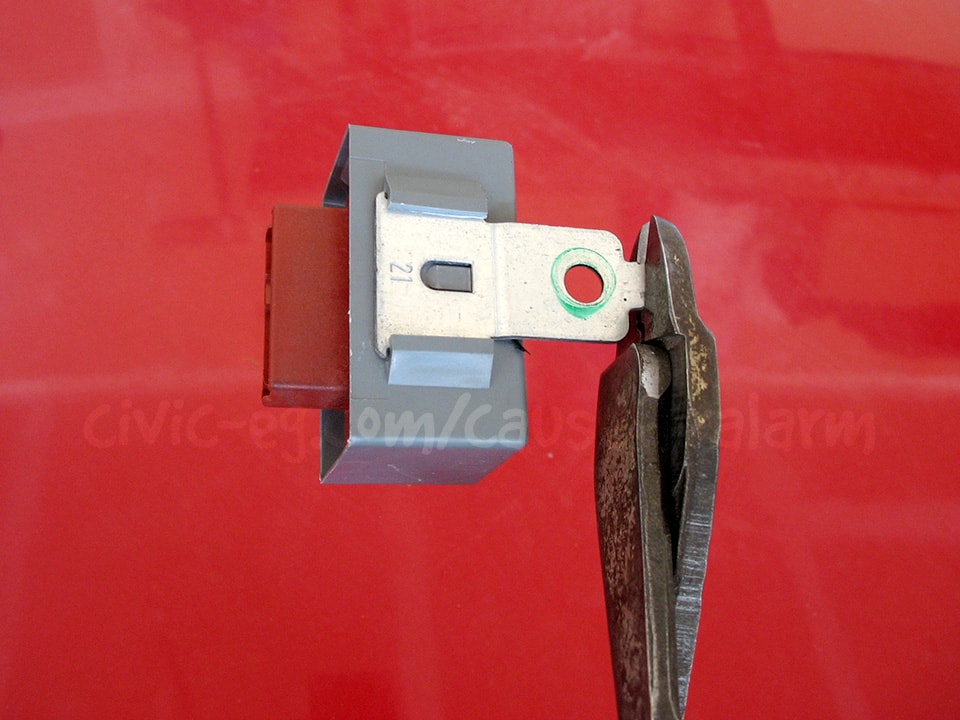
Undo the white retaining piece and move it out of the way. From the front of the plug, push the little tab inside off the wire's pin. Pull the pin out of the plug harness. Tuck this wire away with the other wires, then insert your new ground pin in it's place. Extend this wire to your switch to ground, or to a start kill relay controlled by the alarm.
It's common for there to be two black wires going to the same pin in the main relay. If you opt to cut these wires instead of replacing the pin with one from the junkyard, you need to connect the two cut wires on the car side of the harness. Slide a piece of heat shrink over them and then tape them to the wire bundle.
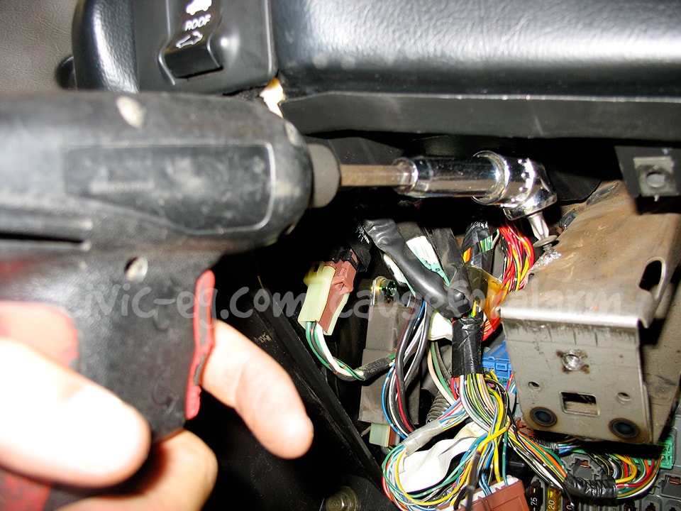
Obviously you need to support this angle driver. I took my hand off to snap the pic.
I had to straighten the bracket to mount flush.
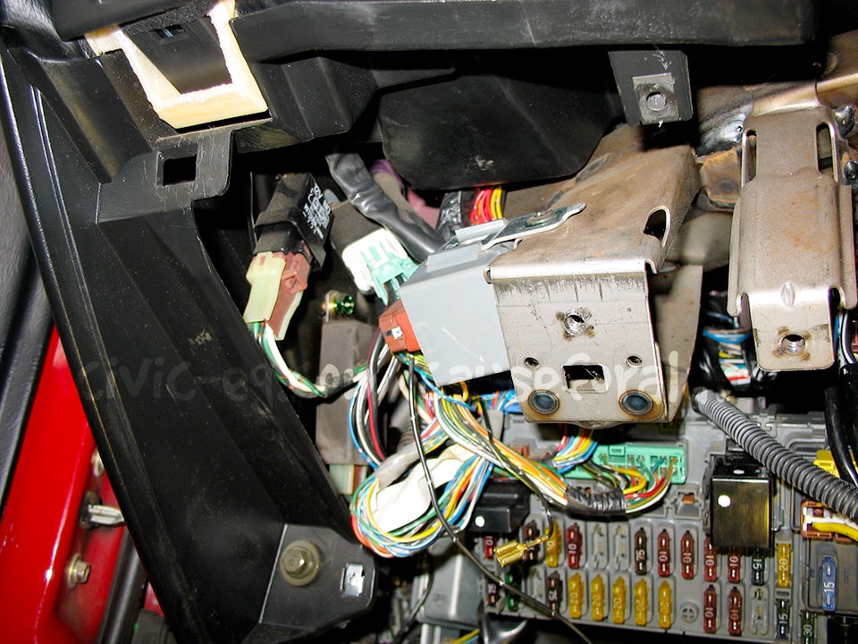
Here are some examples of where you can relocate the main relay.
Door Locks
If your car has power door locks, you will want to hook up the keyless entry. If your car has manual locks, you can install aftermarket actuators (recommend 2 wire), convert to power door locks, or just not have keyless entry at all.
Power Door Locks
If your car came with factory door locks, you simply have to connect the 22 gauge green and blue wires to them in the driver's kick. Connect the alarm's green negative door lock wire to the car's black/white, and the alarm's blue negative unlock to the car's black/red. If you have problems finding these wires you may have to go directly to the control unit or switch in the driver's door.
Some DEI alarms come with the 451M built into the alarm brain and a 7 pin harness for the door locks. In that case, wire it up as follows (de-pin the wires marked in red):
- H3/A - Black/White to Ground (domelight)
- H3/B - White/Black
- H3/C - Green/Black to Lock wire
- H3/D - Violet/Black to Ground
- H3/E - Brown/Black
- H3/F - Blue/Black to Unlock wire
- H3/G - Violet to Ground
Aftermarket Actuators
Some of DEI's alarms have a seperate door lock harness with 7 wires. (1 is for the domelight so it doesn't really count. Just ground it.) Some come with a seperate 451M double relay pack with a 3 pin plug for the alarm. Both are wired the same way. DEI takes care of the 85's and 86's for you.
- Violet - Constant 12v
- Blue/Black - Unlock wire on actuator
- Brown/Black - Ground
- Violet/Black - Constant 12v
- Green/Black - Lock wire on actuator
- White/Black - Ground
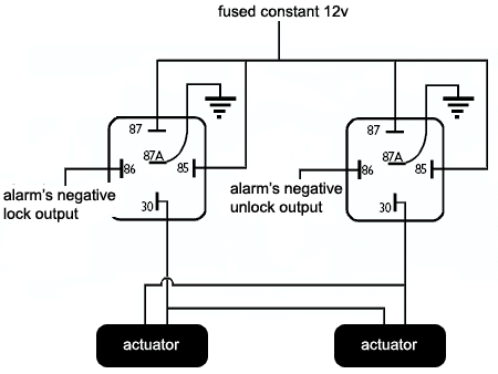
Using Two Relays Instead of the 451M
Visual Guide for Patreons
The alarm installation guide available on my Patreon page is in constant development to make it easy to understand what your wiring should look like. It covers all possible scenarios with door locks, actuators, converting to driver's priority unlock, bypassing/removing the OEM doorlock module. It details start kills and the rest of the alarm wiring as well. Support Cause for Alarm and gain access to the guide today!
Trunk Pop
Use an aftermarket doorlock actuator for trunk pop. "Trunk Pop Actuators" are far too huge for this.
The actuator will fire in only one direction, and then return to rest or be pulled back by a small spring that you install. The direction you mount the actuator will determine which polarity you need. Ground one actuator wire to the chassis. Connect the other wire to the output of your relay (not included).
- Trunk Pop Relay
- 86 RED/WHT - aux output on alarm main harness
- 85, 87 RED Constant 12v input on backup battery harness
- 30 Actuator
- Actuator's other wire goes to chassis ground
Testing the Alarm
Close the doors and trunk and arm the alarm. Make sure both doors lock when armed, unlock when disarmed. Also make sure the parking lights and LED flash. Make sure both sirens chirp. Unlock the door with the key and make sure it triggers the alarm, then test the other door and the trunk. Make sure the car wont start when the alarm is going off, but will start when it's disarmed. Try putting the alarm in valet mode and taking it out (turn the key on but the engine off and tap the valet button).
Program the Valet Button
By default it takes one press on the valet with the ignition on to put the alarm in valet. Program it for 2 or more presses and write it down in the booklet, or just program whatever options you want and then remove the valet button altogether.
Once you are satisfied that the alarm is fully functional, put your interior back together and give it one more quick test.
Troubleshooting Common Mistakes
- Problem: Alarm doesn't respond to remote.
- Solution: Check the alarm's power and ground, power fuse, and that the antenna is plugged in all the way. DEI's paging alarms that don't have remote start have the ability to program a single remote to control four cars. Look for the little number icon. It can be anything from 1-4 but should be set to 1. You can change it by pressing the little blue button on the back of the remote.
- If it's a used alarm, you may need to reprogram the remote to the alarm using the key and the valet button (refer to the manual).
- Problem: Only the driver's door triggers the alarm.
- Solution: You tapped into the driver's side door trigger. The other doors are upstream of this wire. Tap into the passenger-side door trigger instead.
- Problem: Alarm doesn't trigger the door locks.
- Solution: Both the lock and unlock wire must be connected for the door lock system to work.
- Problem: Doors lock on disarm, unlock on arm.
- Solution: You have the lock/unlock output wires reversed.
- Problem: Alarm worked initially, but now it doesn't go off.
- Solution: Cycle the ignition. DEI alarm's have nuisance protection, so if you keep triggering a zone, eventually it will ignore that zone until you have cycled the ignition (turn the key on and off).