
F23 Swap Guide
Out Now!
Stealth Car Alarm Install
1988-1991 Honda CRX
You can expect to have your interior taken apart anywhere from 4 hours to an entire weekend. This install is similar to any DEI alarm going into any 2 door Honda/Acura roughly between the years of 1988 and 2005.
Alarm Bench Prep
OEM Wire Colors
| WIRE | COLOR | LOCATION |
|---|---|---|
| 12 VOLT CONSTANT | WHT | FAR LEFT PIN ON FUSEBOX |
| STARTER | BLK/WHT | STARTER RELAY |
| IGNITION | BLK/YEL | IGNITION HARNESS |
| PARKING LIGHTS (+) | RED/BLK | DRIVER'S RUNNING BOARD |
| DOOR TRIGGER (-) | GRN/RED | DRIVER'S RUNNING BOARD |
| TRUNK TRIGGER (-) | GRN/BLK | DRIVER'S RUNNING BOARD |
All wires must be verified with a multimeter. Main relay is on the driver's side above the fusebox. A T40 torx bit is required to remove the plastic trim in the running boards on some model years.
Choose a location
Center Console
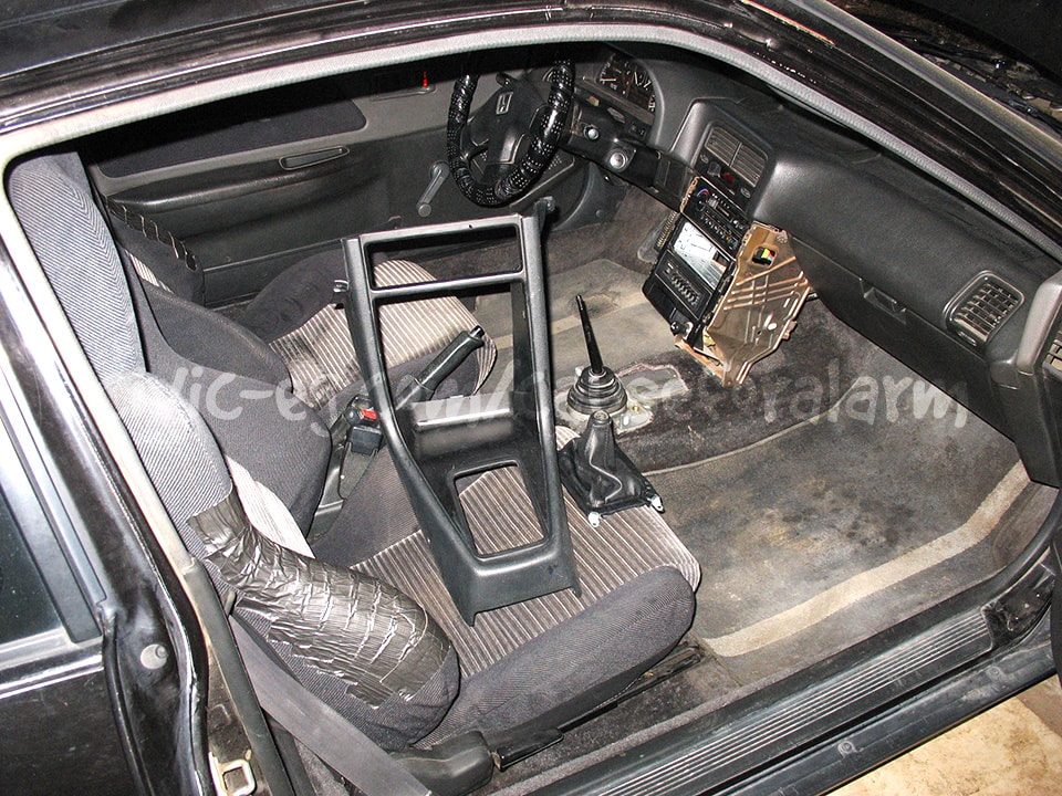
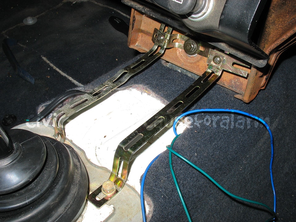
This support was made with car stereo backstraps, a couple screws and some speed clips.
- Pros
- Minimal interior disassembly
- No need to extend wires
- Cons
- Vulnerable if located
- Wiring requires extra careful concealment
- Cramped space for alarm components
Rear Quarter (either side)
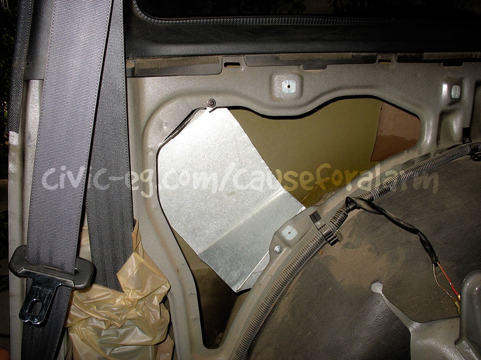
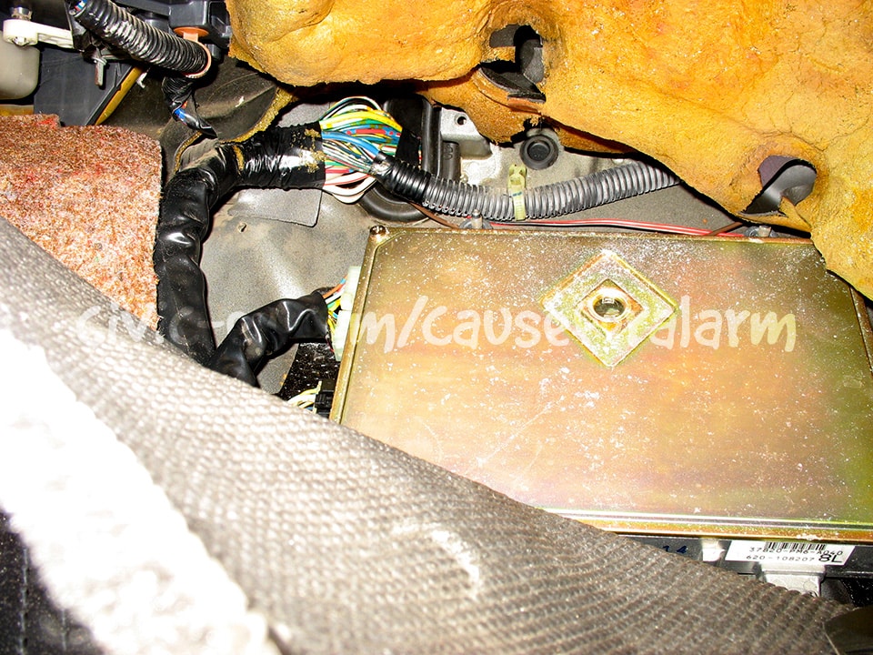
I made a sheet metal tray to mount the alarm. These days I actually construct a box to house the alarm and components. Check the Alarm Preparation page for more info.
- Pros
- Difficult for thief to gain access
- Difficult for thief to locate
- Wiring doesn't give away location
- Completely unexpected
- Lots of space for alarm components
- Cons
- Requires major interior disassembly
- Requires some wire extension
- Time consuming
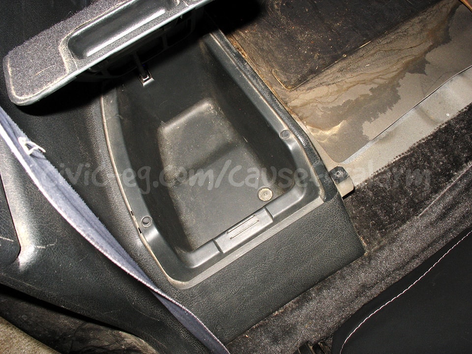
Under storage compartment
There isn't any free space under or around the storage compartment. Putting the alarm inside the compartment itself would require significant damage to plastics and be of no benefit to stealth.
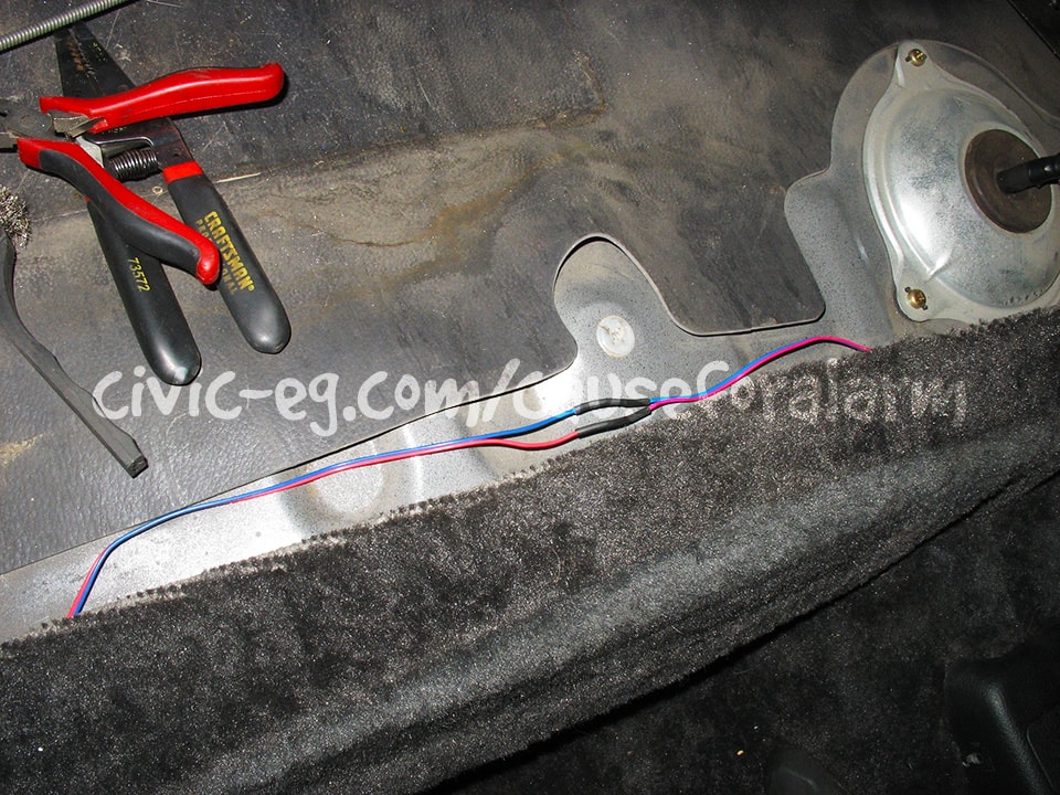
Sides of trunk (under rear quarter)
All the pros/cons of a rear quarter install and just adding a couple feet to the wiring. A viable option.
Alarm Peripherals
The best way to start the install is to first get all of the alarm peripherals out of the way. Do these incrementally on weekdays leading up to a weekend install. These include the siren, antenna, valet button and LED, and the hood pin. You can mount trunk and door actuators at this time.
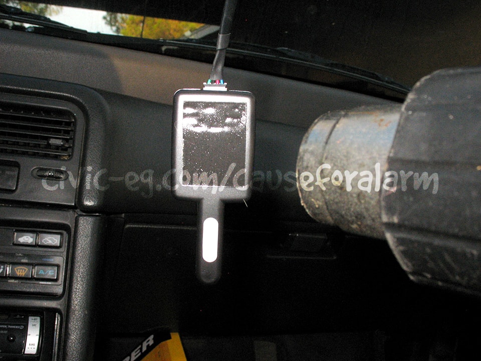
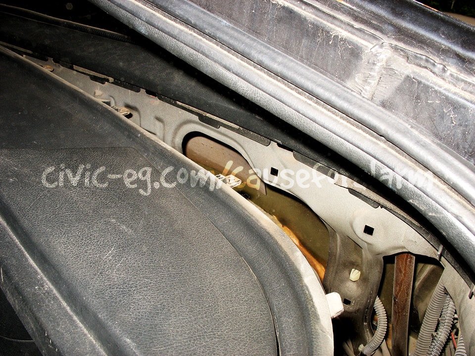
Antenna
For the best possible range, mount the antenna up high on the glass. Metallic tint or defroster wires can diminish the signal. Tuck as much of the wire up high as is possible, and wrap the excess length loosely under the pillar plastic. Don't bundle up the wire down near the alarm.
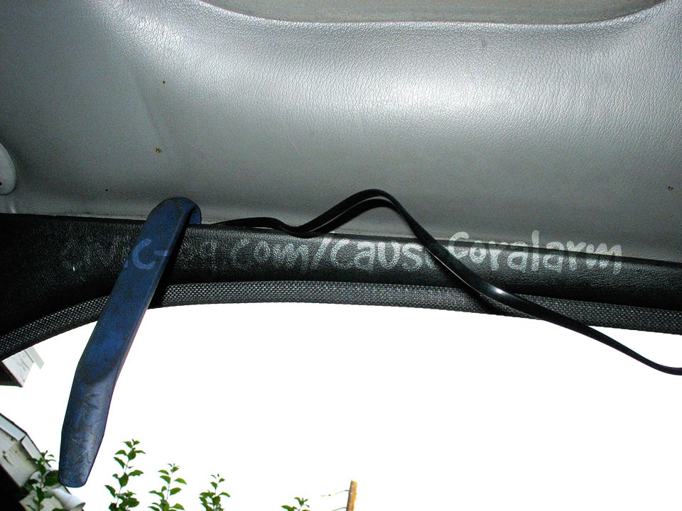
The trick to getting double-sided tape to stick forever is to 1) Clean the surface with alcohol and 2) Heat the tape for a 4-5 seconds until it looks sweaty.
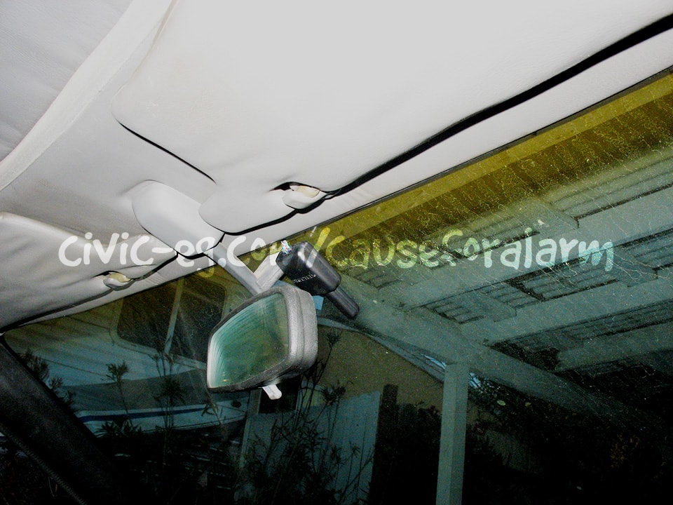
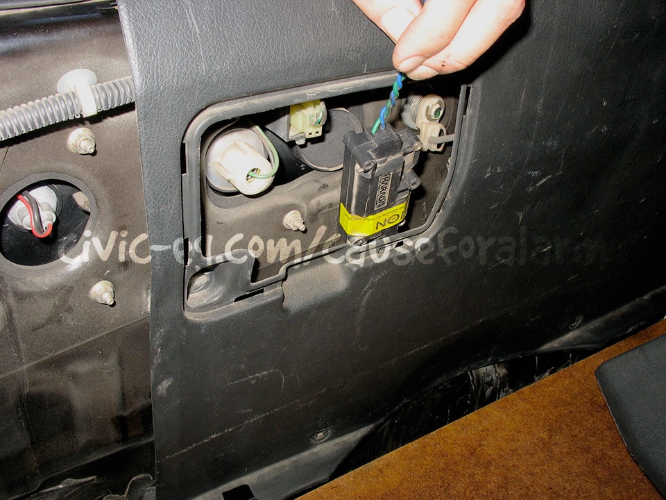
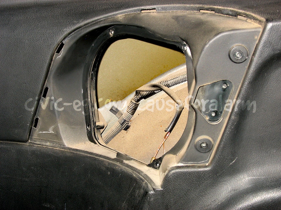
LED
Rear quarter panel installs require you to extend the LED's 22 gauge wires. These are wires worth concealing because they leave a trail back to the alarm. I used an oem plug connector so I could disconnect to remove the panel if necessary. I have a box full of spare harnesses that I use for things like this.
The best mounting place for the LED is a pop out panel that is easily visible from outside the vehicle. Drill a hole using a 1/4 bit. The manual says 9/32, but this leaves the LED loose. Force the LED in place using a padded surface like a stack of cardboard on a workbench.
Valet Button
The hole for the valet button is the same as the LED. You want it hidden, but you need access to it to program new remotes. You can put the alarm into valet mode by hitting lock, unlock, lock quickly in sequence on the remote.
Hood Pin

Siren
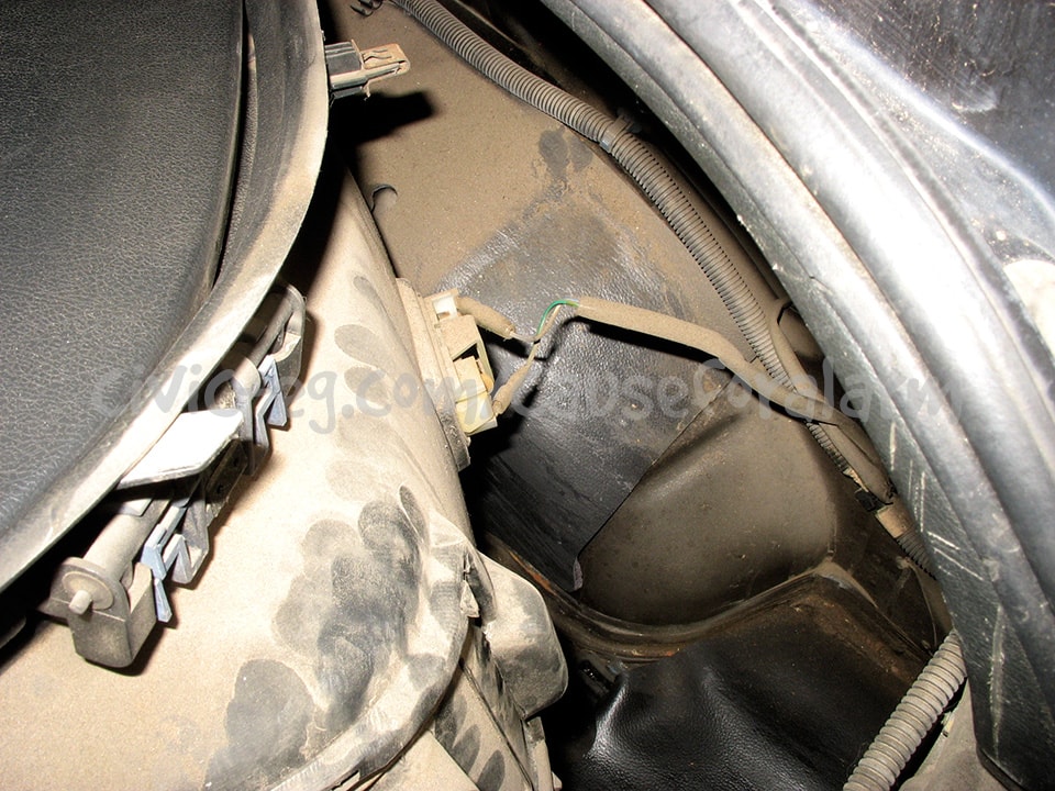
Find a suitable hiding place, then install the siren in the engine bay using metal tapping screws. Consider the spaces under the front fenders, or under the battery tray.
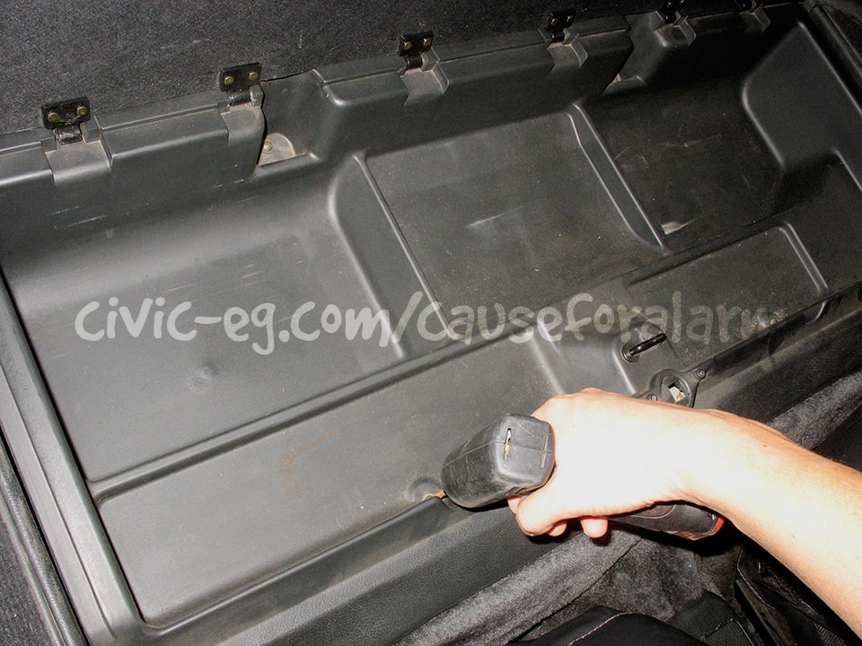
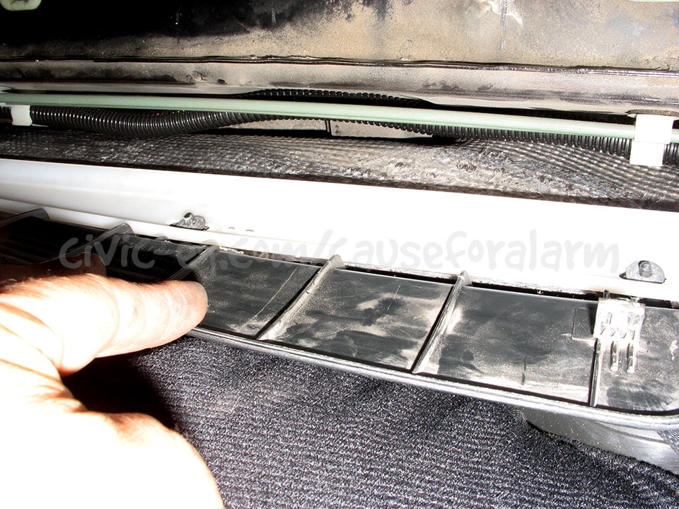
Trunk Actuator
First I checked if the actuator would clear the trunk plastic. Then I mounted it checking that the screws didn't penetrate too far on the other side. Then clean the area and seal the screws with hot glue. It's the most convenient and long lasting option I have found.

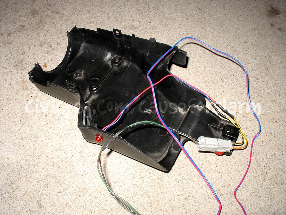
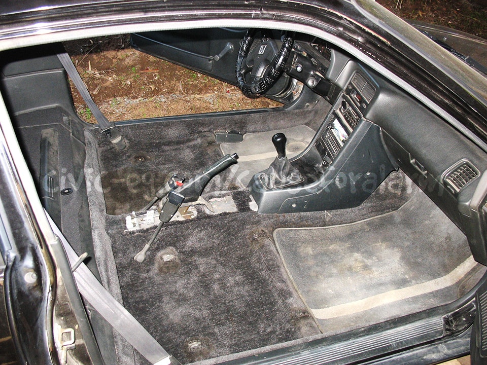
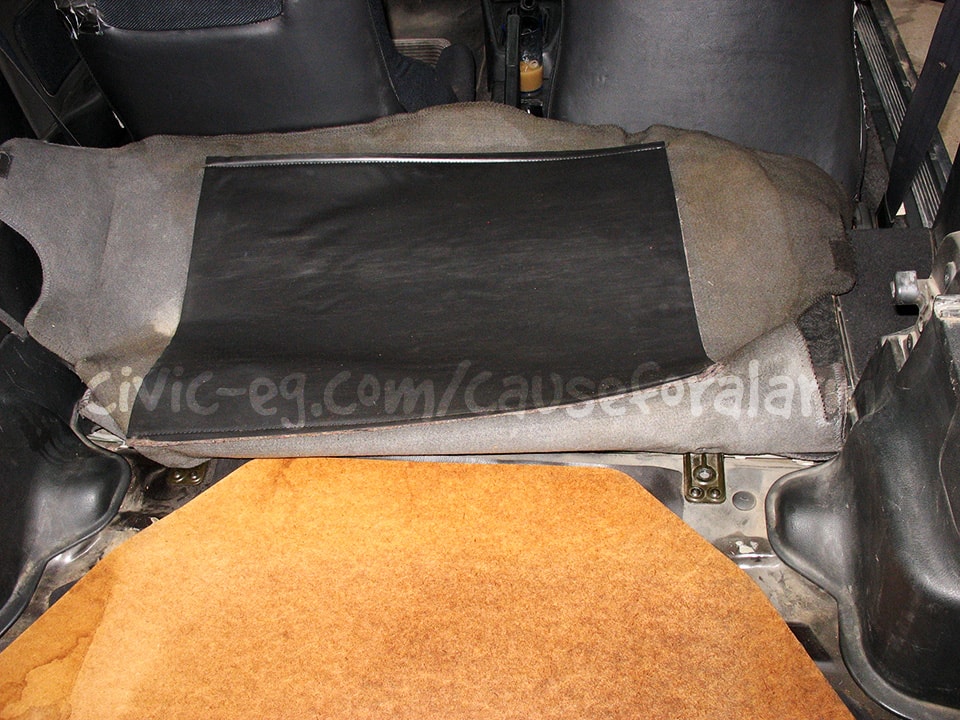
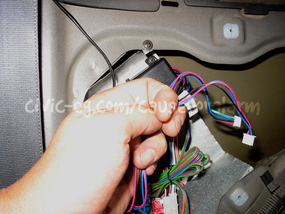
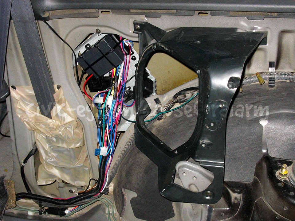
Interior Disassembly (rear quarter install)
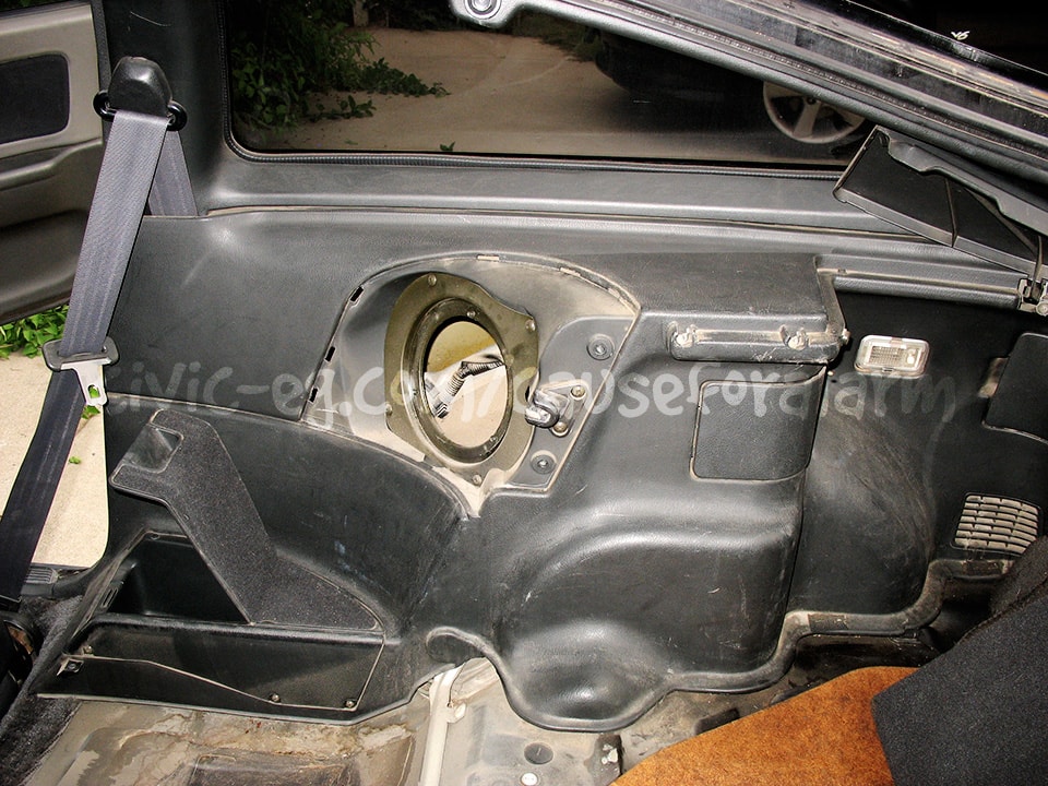


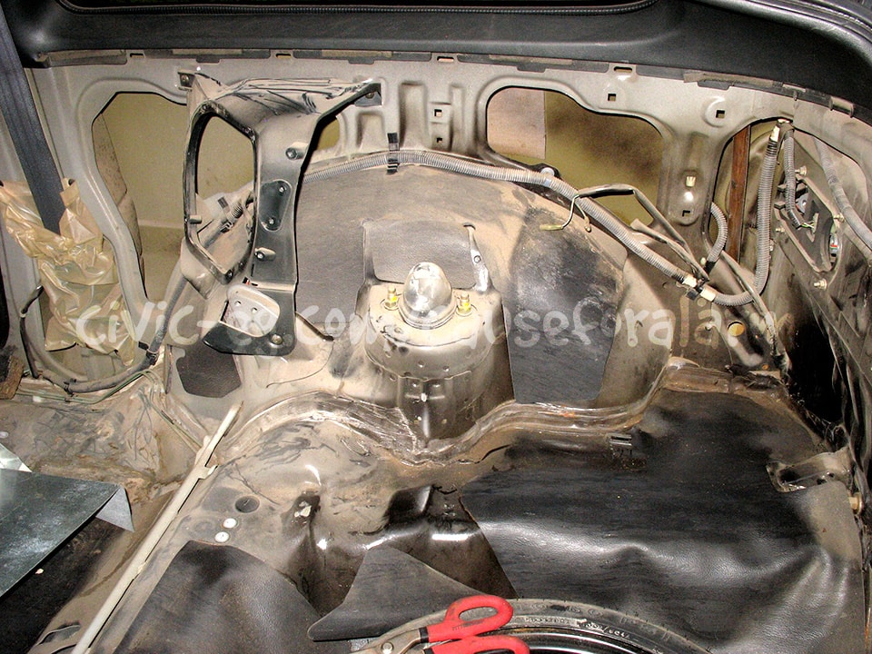
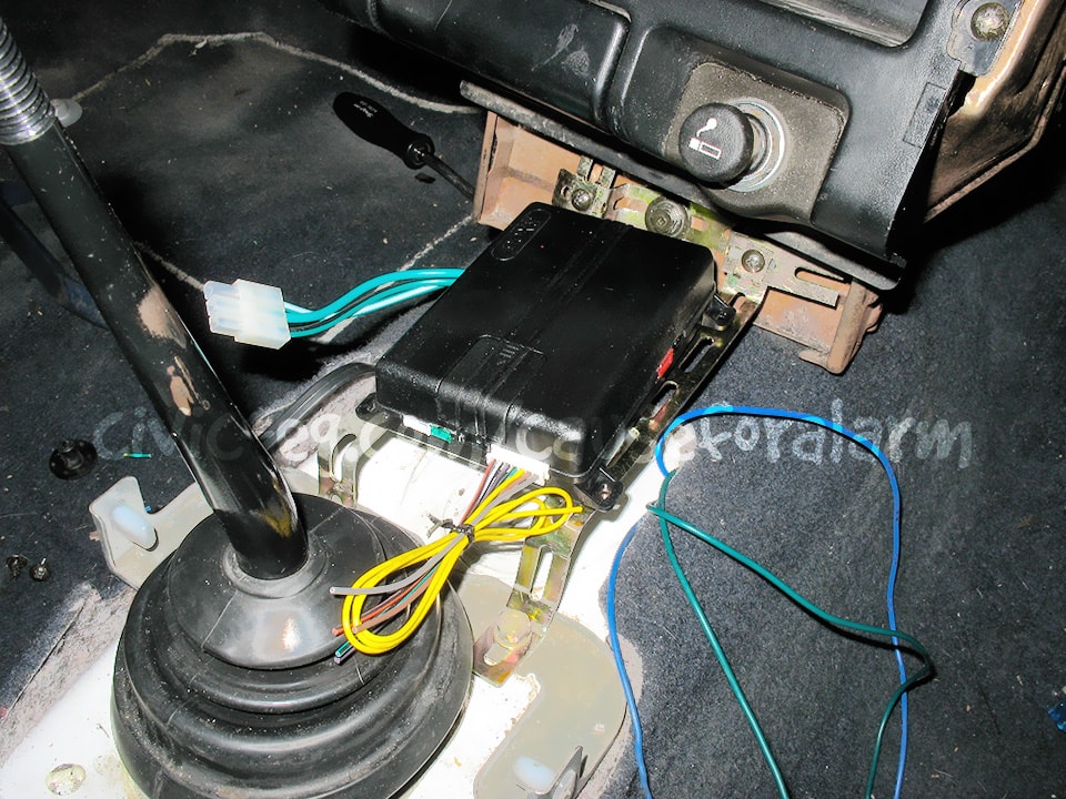
Mount the alarm and components
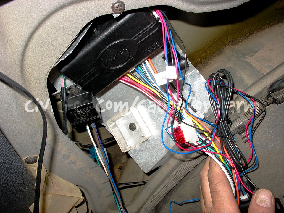
I made a sheet metal tray and mounted everything to it. The backup battery is double-sided-taped to the alarm brain and then supported with zipties. More recently I've developed a method of putting everything into a sheet metal box and doing the majority of the wiring on the bench. Details can be found in the "Alarm Preparation" area of this site.
Battery Backup and Additional Sensors
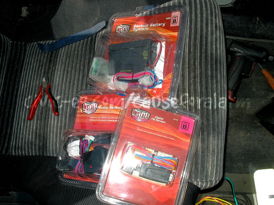
The battery backup module is easy to wire but difficult to explain in words. This is one of the main inspirations for drawing up my visual guide. All tiers of Patreon support get access. You installation will turn out better and you'll learn more if you GET YOURS NOW.
The battery that comes with the module is not very reliable. I recommend upgrading to the 1212 battery linked to on the Bench Prep page.
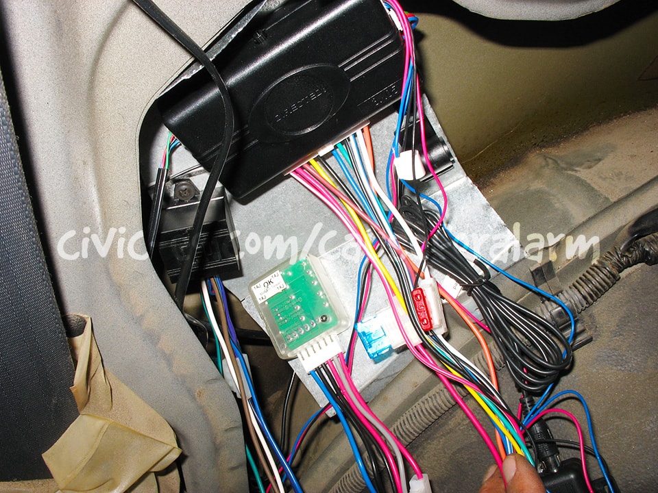
The BLU wire from the alarm is forked out with diodes to keep the battery backup, hood pin, and trunk trigger separate. Otherwise, the hood pin and battery backup would turn on your trunk open warning light on the dash. The stripes on each diode face the sensor, and the opposite ends are twisted together and connected to the BLU wire on the alarm.
The RED wire from the alarm goes to the battery backup RED only. The battery backup GRAY then connects to Constant 12v on the car. You can connect any wires needing 12v to this gray wire. That way they wont use the backup battery when the car battery is dead or disconnected.
The BLK wire goes to a ring terminal chassis ground along with all the other wires needing ground.
Tilt and Glass Break Sensors
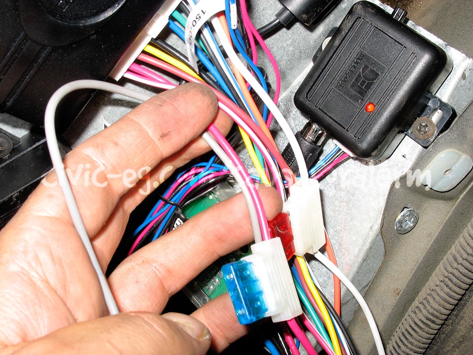
The glass break sensor comes with a split Y harness that you can use for the tilt sensor. The tilt sensor uses a three pin plug though, so it's not plug 'n play. The four pin sensor harnesses are left over from when trigger warning and instant trigger were on separate green and blue wires. DEI then began looping the green wire to the blue wire, as brief pulses on the blue wire will trigger a warning.
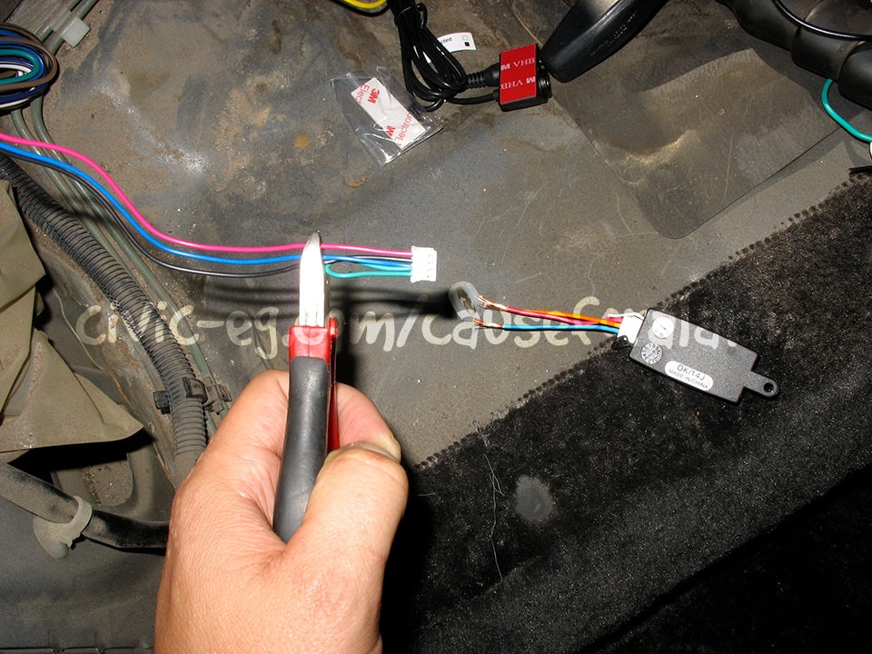
With the Y harness unplugged from the alarm, cut this four pin plug off (note the GRN loop). Cutting live wires in a bundle would short them across the tool.
Then wire to the tilt harness as shown (note ORN to BLK). The ORN wire is DEI's convention for Ground-When-Armed, meaning the tilt sensor is inactive unless the alarm is on.
The bottom branch of the Y harness MUST be plugged into the alarm! If you'd like to stretch the Y harness into an |, you must connect the blue and green wires in the center so that the signal gets from each sensor to the alarm. Follow these wires from end to end to grasp my meaning.
The tilt sensor should be mounted parallel to the floor of the car and secured tightly.
Red - Power Constant 12V
DEI 520T Battery Backup
Connect to a constant 12v power source under the dash to the included inline fuse. This wire then connects to the red wire on the 520T backup module. The module's gray wire then connects to the alarm's red wire.
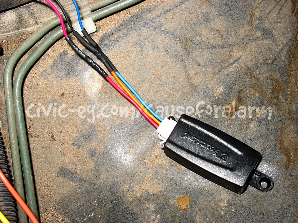
In the preparation stage, the fused red wire is cut from the alarm harness and attached to the car, then extended back to the backup module.
I'm developing an alarm install guide full of visual representations and diagrams to convey this and other parts of the install more clearly. It is available to Patreon Supporters at patreon.com/boyshit.
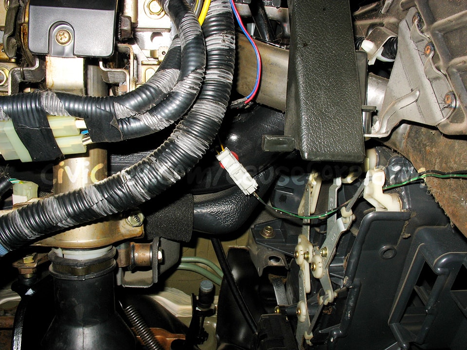
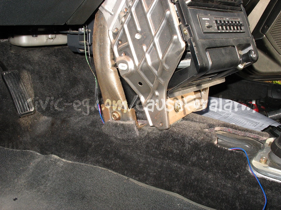
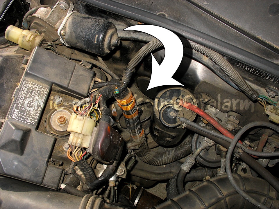
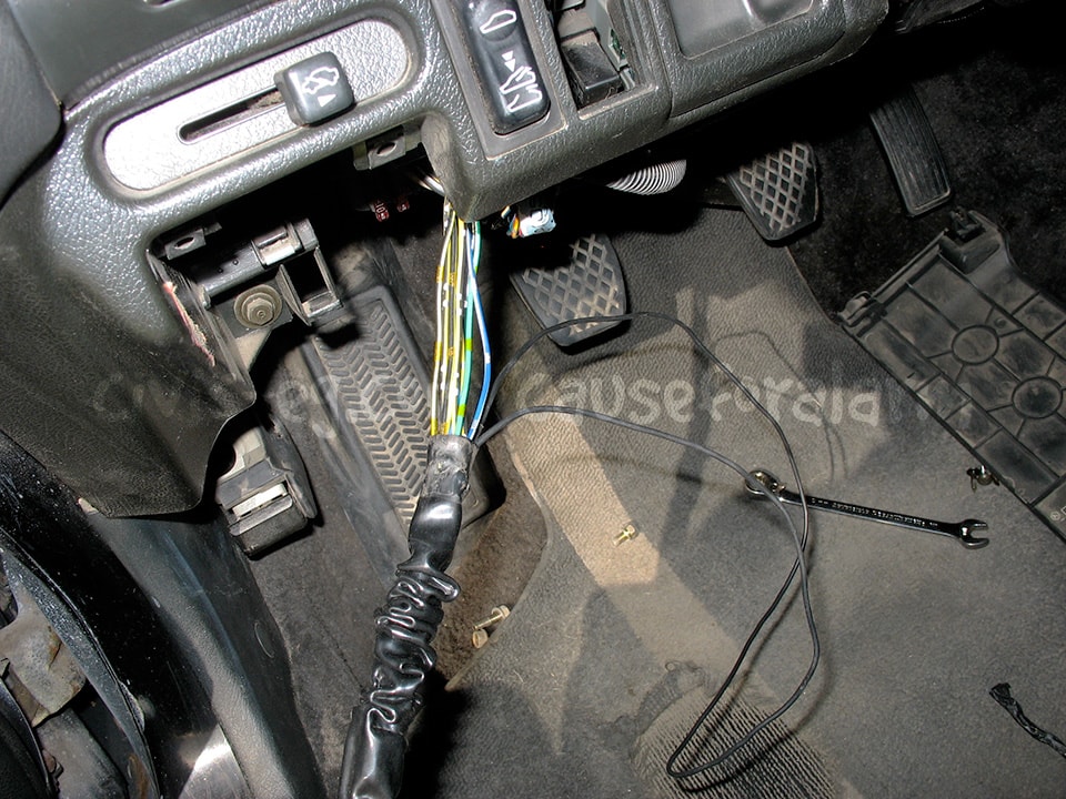
Yellow - Ignition 12v
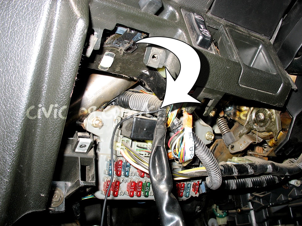
On Hondas, a true ignition 12v appears as a blk/yel wire. The most trustworthy connection being the 10 gauge blk/yel wire on the ignition harness going into the under dash fuse box. Hiding this connection can be tricky. Tap the connection near a fusebox plug harness and use small diameter split loom and electric tape.
Blue (18 ga.) - Instant Trigger (-)
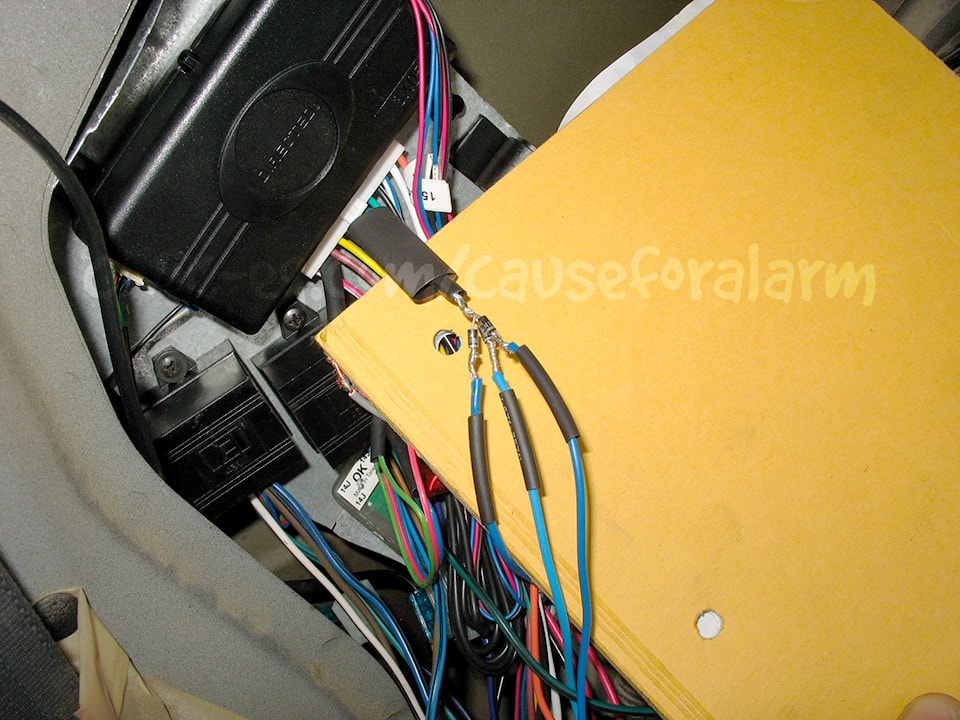
This connection is intended for the car's trunk open indicator light on the gauge cluster. This is the wire to add the hood pin and battery backup trigger to as well, but you want to keep each circuit separate so that they don't all trigger the gauge light. To do that, you need diodes.
Diodes allow electricity to flow in only one direction. Fork this wire out as shown and connect the trunk trigger, hood pin, and battery backup individually. The striped ends of the diodes point toward each sensor (hood pin, trunk wire, 520T blue wire), and the other ends are tied together and then soldered to the alarm's blue negative trigger wire. Use a piece of heat shrink on each connection, and then a larger piece on the alarm side to enclose the entire fork.
Start Kills / Killswitch (ECU)

Thieves expect a starter kill and they know how to get around it. There are many other ways to prevent a car from starting. Cutting just the ignition or just the fuel isn't much better. Choose two circuits for the alarm and add a separate kill switch on a third circuit.
The alarm requires a relay for each circuit you want to kill. One relay is included and is intended for the starter. You can get a 2nd relay and harness for a 2nd start kill, but I like to use a 451m. It's two pre-wired relays in one module. It was intended for certain door lock applications and used to be included with many Viper alarms. No thief will recognize how I've used it here.
For folks new to wiring I have printable wiring representations at patreon.com/boyshit. It doesn't work posting it here because there are multiple start kill scenarios. The guide is under constant refinement based on user's questions and input. For a couple bucks I hope you'll consider supporting this tremendous effort.
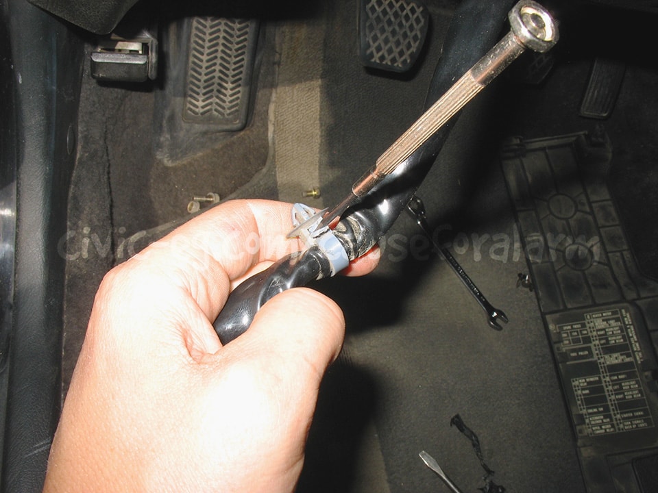
Start Kills / Killswitch (Main Relay)
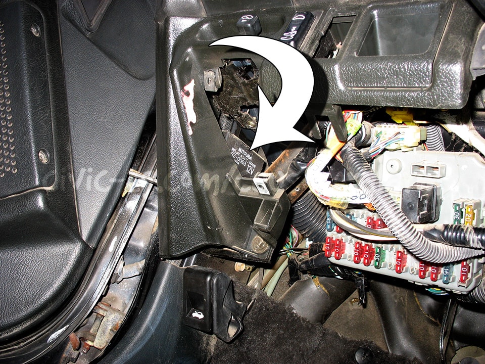

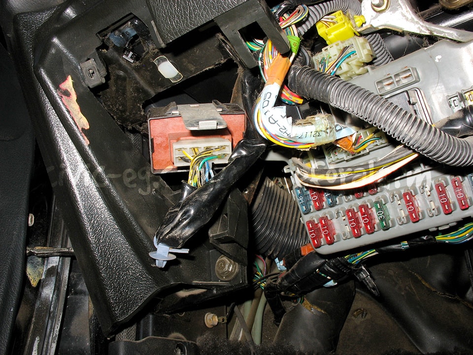
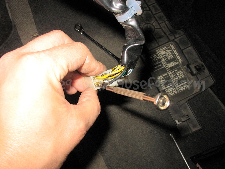
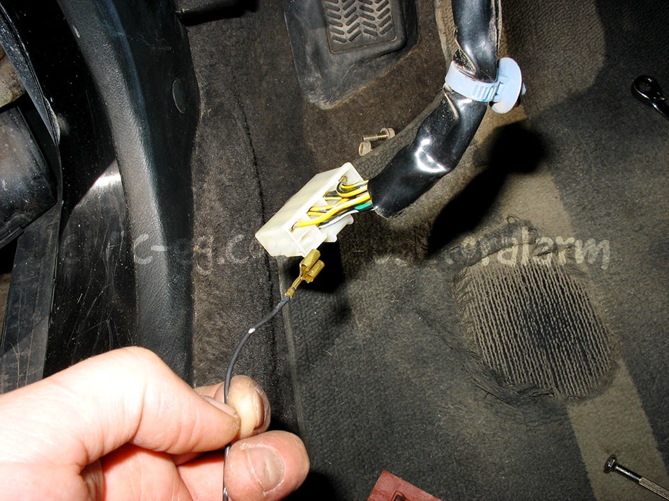
Cutting the ground wire is fine. Another option is to de-pin the ground, tuck it away, and insert a new pin you got from the junkyard. Run this wire through your kill switch or start-kill relay and then on to chassis ground.
A flexible plastic tab pushes the metal pin down so that the slot on the top of the pin fits into a protrusion in the housing. The key to depinning is to lift the flexible tab and then lift the metal pin toward the tab and off the protrustion, then pull the pin out.
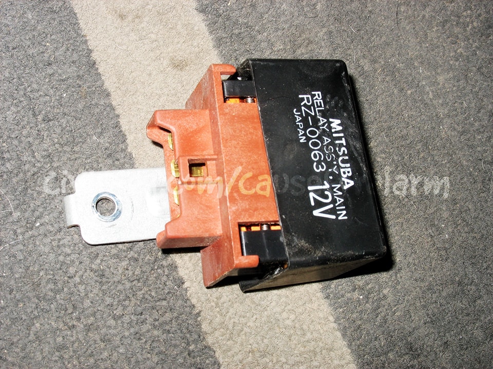
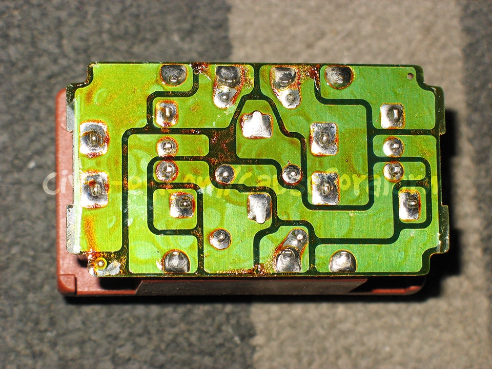
Early EFI Hondas are known for their weather-related intermittent start condition caused by cracked solder in the main relay. Now is the time to reflow the solder. Clean off the dielectric grease so you don't burn it and contaminate all the joints. Warm it with the heat gun and wipe it or blow it off with compressed air into a rag.
Get the soldering iron hot, tin it, then press it to each joint until it's molten. Flux can be very helpful here. Use a metal brush on the iron and tin it each time. Do not accidentally bridge any of the traces by adding too much solder or carrying it from one joint to the next.
Remove the loop tie so you can hide a new ground wire in the bundle. In order to reuse it, pry the tab up on the loop tie and push the end through.
Fish an 18 gauge wire through this loom. Solder it to the pin you added or to the relay side of the cut ground wire. Reinstall the main relay, then run this wire to your switch to ground or to the alarm's start kill relay.
Locating connections on the car
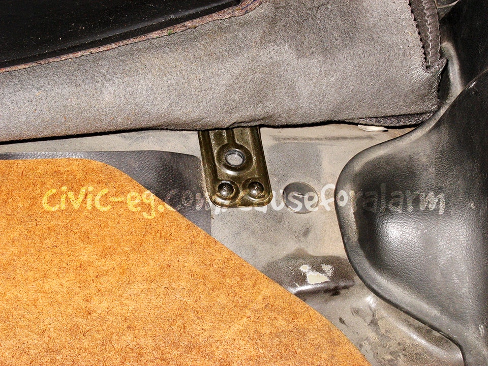
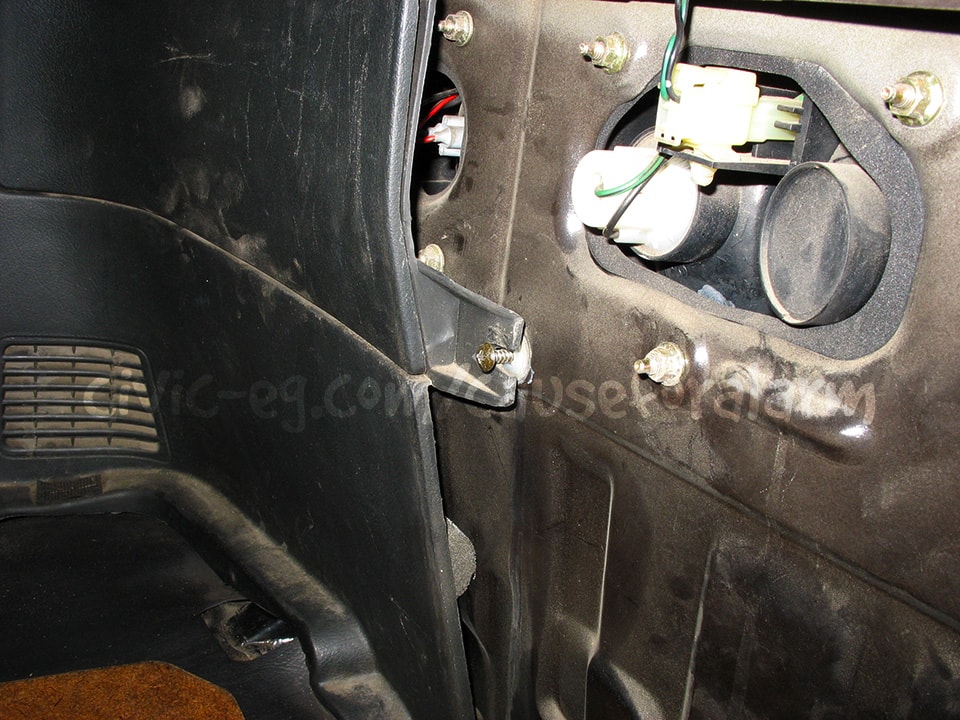
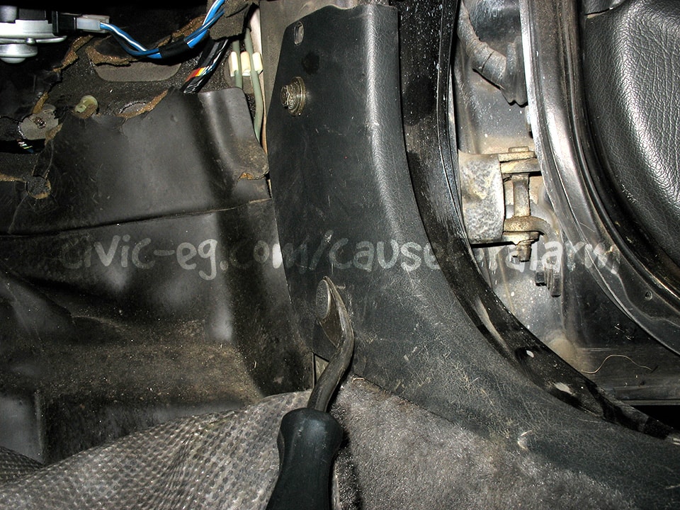
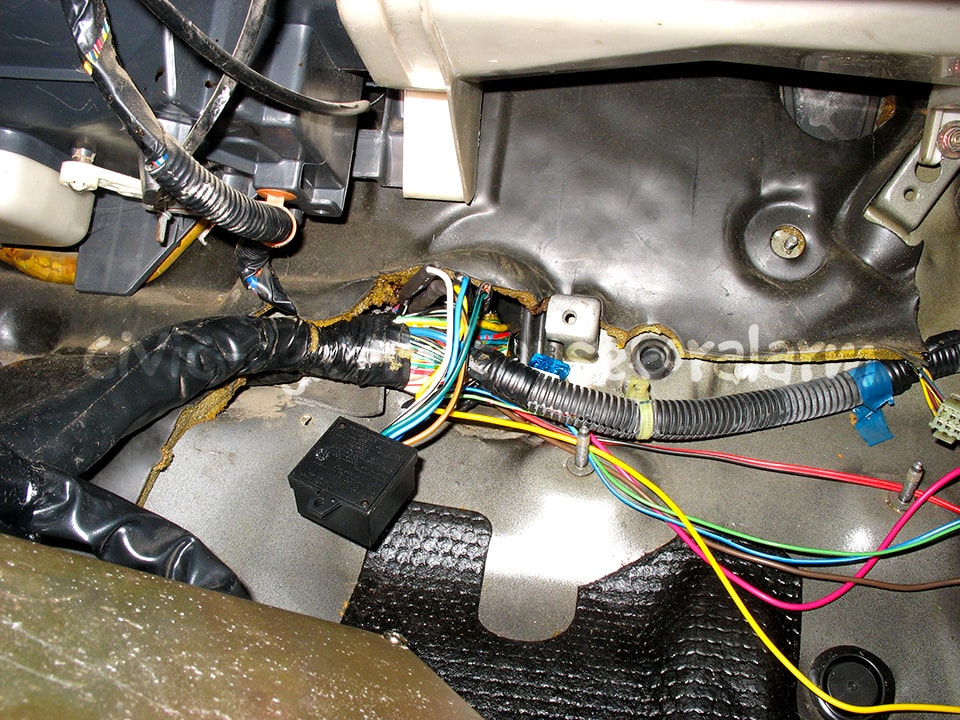
Door trigger, Trunk trigger, Parking lights
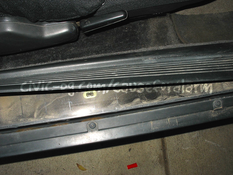
Pry the running board plastics up right at the clips and try to prevent the metal retainers from staying in the plastic plugs in the door sill. They're difficult to remove and put back on the cover side, and if you don't do that, they wont stay down.
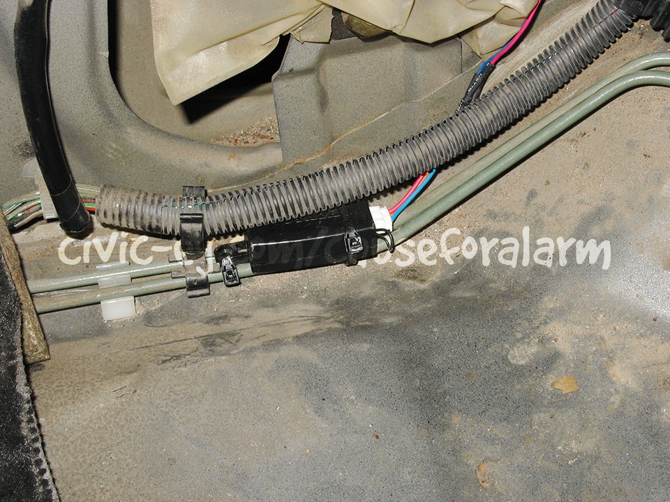
Connections for the door trigger, trunk trigger, and parking lights can all be found in the harness alongside the running boards. This is also where you'll be running your loomed alarm wires for the remaining connections at the dash and to the hood pin and siren.
Door Trigger (-)
The door trigger is an obvious wire. You can follow the wire down from the passenger side door switch. You use the passenger side to detect all doors. Note that these type of switches commonly fail. If the dome light isn't working and it's not the bulb, or if it works on only one door, it's worth trying to fix the switch. Sometimes you can simply scrape off the corrosion.
Close all the doors, set your meter to continuity, connect one probe to chassis ground and the other to the suspected wire. There should be no continuity (meter shows 1). Open a door and the meter should drop to 0 and chime. Test each door individually.
Parking Lights (+)
The parking light wire is also easy to find. It rests at 0 volts and jumps to battery voltage when you rotate the stalk to parking or headlights.
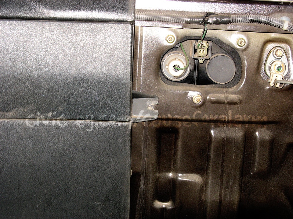
Trunk Trigger (-)
There are usually multiple wires with the same colors as the trunk trigger. Pay attention to the silver dots that repeat on the insulation, and look for the source at the trunk latch. The sensor in the latch sometimes fails. Always test and verify this wire. It's the same as verifying the door trigger.
Testing the Alarm
Close the doors and trunk and arm the alarm. Make sure both doors lock when armed, unlock when disarmed. Also make sure the parking lights and LED flash. Unlock the door with the key and make sure it triggers the alarm, then test the other door, hood and trunk. Make sure the car wont start when the alarm is going off, but will start when it's disarmed. Try putting the alarm in valet mode and taking it out (turn the key on but the engine off and tap the valet button).
Program the Valet Button
By default it takes one press on the valet with the ignition on to put the alarm in valet. Program it for 2 or more presses and write it down in the booklet, or just program whatever options you want and then remove the valet button altogether.
Once you are satisfied that the alarm is fully functional, put your interior back together and give it one more quick test.
Troubleshooting Common Mistakes
- Problem: Alarm doesn't respond to remote.
- Solution: Check the alarm's power and ground, power fuse, and that the antenna is plugged in all the way. DEI's paging alarms that don't have remote start have the ability to program a single remote to control four cars. Look for the little number icon. It can be anything from 1-4 but should be set to 1. You can change it by pressing the little blue button on the back of the remote.
- If it's a used alarm, you may need to reprogram the remote to the alarm using the key and the valet button (refer to the manual).
- Problem: Only the driver's door triggers the alarm.
- Solution: You tapped into the driver's side door trigger. The other doors are upstream of this wire. Tap into the passenger-side door trigger instead.
- Problem: Alarm doesn't trigger the door locks.
- Solution: Both the lock and unlock wire must be connected for the door lock system to work.
- Problem: Doors lock on disarm, unlock on arm.
- Solution: You have the lock/unlock output wires reversed.
- Problem: Alarm worked initially, but now it doesn't go off.
- Solution: Cycle the ignition. DEI alarm's have nuisance protection, so if you keep triggering a zone, eventually it will ignore that zone until you have cycled the ignition (turn the key on and off).