
F23 Swap Guide
Out Now!
Stealth Car Alarm Install
1996-2000 Honda Civic
Alarm Bench Prep
OEM Wire Colors
| WIRE | COLOR | LOCATION |
|---|---|---|
| 12 VOLT CONSTANT | - | DASH FUSEBOX OPTION OUTPUT |
| STARTER | BLK/WHT | STARTER RELAY |
| IGNITION | BLK/YEL | BROWN PLUG ABOVE FUSEBOX |
| PARKING LIGHTS (+) | RED/BLK | DRIVER'S RUNNING BOARD |
| DOOR TRIGGER (-) | LT GRN/RED | DRIVER'S RUNNING BOARD |
| TRUNK TRIGGER (-) | BLU/BLK | DRIVER'S RUNNING BOARD |
| FUEL PUMP (+) | YEL/GRN | DRIVER'S RUNNING BOARD |
| POWER LOCK (-) | GRN/WHT | SIDE BLUE PLUG ON DASH FUSEBOX* |
| POWER UNLOCK (-) | GRN/ORN | SIDE BLUE PLUG ON DASH FUSEBOX* |
All wires must be verified with a multimeter. Main relay is on the passenger side beside the glovebox. *99-00 Civics have a door lock module below the hood release handle.
The Process
This is the best way to install a car alarm.
Install a Kill Switch
Day One upon taking ownership of the car, install a hidden kill switch. If you're beyond Day One, do it now. The main relay is a good choice. The fuel pump or starter are very poor choices.
Buy the Right Equipment
- Viper Alarm
- Audio (Glass Break) Sensor
- Battery Backup
- Upgrade the Battery
- Tilt Sensor
- Hood Pin Switch
- Auto Relays or 451M Modules
- Tools and Supplies for a Professional Install
Links to everything you need can be found on the Bench Prep page.
Bench Prep the Alarm
Gather the alarm brain, upgraded backup battery, backup battery module, audio sensor module, door lock relays or 451Ms (if necessary), and trunk pop relay (if necessary) and stack them together in the shape of a brick. Use tape and zipties to keep them in shape temporarily.
Wire the backup battery module, tilt and audio sensors, door lock relays, and trunk pop relay together. Gather the wires that connect the car into a single bundle wrapped in 3/4" split loom.
Design and create a box to house the alarm and components. Thin sheet metal and foil tape work well. This box should have two flaps for mounting screws. Leave a quarter inch of free space on all sides that have harnesses or adjustment knobs. Plan to line the box with cardboard. Choose a place to cut an exit hole for a 3/4" split loom to wrap the wires connecting to the car (including the antenna wire, tilt sensor harness, and glass break mic wire).
Install the Alarm Peripherals
- Siren(s)
- Hood Pin
- Antenna, LED, Valet Button
- Start Kill
- Tilt Sensor
If you can install these things days in advance of the alarm installation, your day will go much easier.
Complete the Installation
- Remove Seats
- Remove Interior Plastics as Necessary
- Finalize Location and Mount the Alarm Box
- Locate Connections to the Car
- Group and Run the Wiring
- Start with Power and Ground
- Connect the Peripherals to the Alarm
- Verify Connections as you Wire the Alarm to the Car
- Test Every Function Before and Again After Reassembling the Inerior
Choose Location
Rear Quarter Panel, Either Side (Coupe or Hatchback)
Under the Rear Seat
Don't spill anything or seat very large persons.
Inside the Rear Door (Sedan)
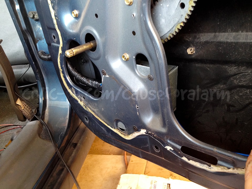
Difficult to drill holes for the alarm wires and then weather proof them, but an excellent location otherwise.
Also weather proof the alarm box with foil tape!
Alarm Peripherals
The best way to start the install is to get all of the alarm's peripherals out of the way. This includes both sirens, the antenna, the valet button and LED, the glass break and tilt sensors, the hood pin, and the backup battery.
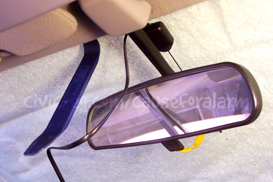
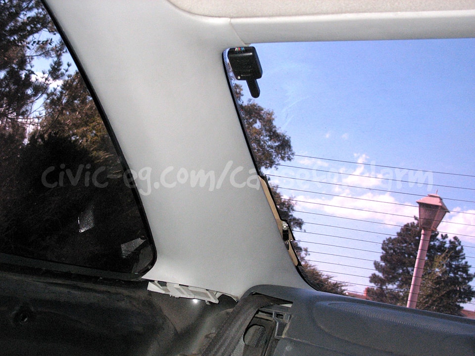
Antenna
Here are some optional positions for mounting the antenna. For the best possible range, mount the antenna up high and tuck any excess length loosely in the headliner. Never tightly bundle up the wire or range will suffer.
Windshield
Rear or Side Glass
Hood Pin Switch
This is only ever included with remote start alarms, but you can get one dirt cheap and add it to any alarm. This is the only way you'll detect a thief popping your hood to disconnect your battery and steal your parts.
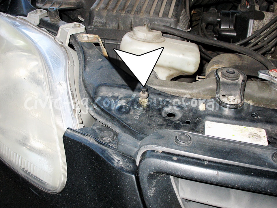
Use an existing hole with some washers. Or...
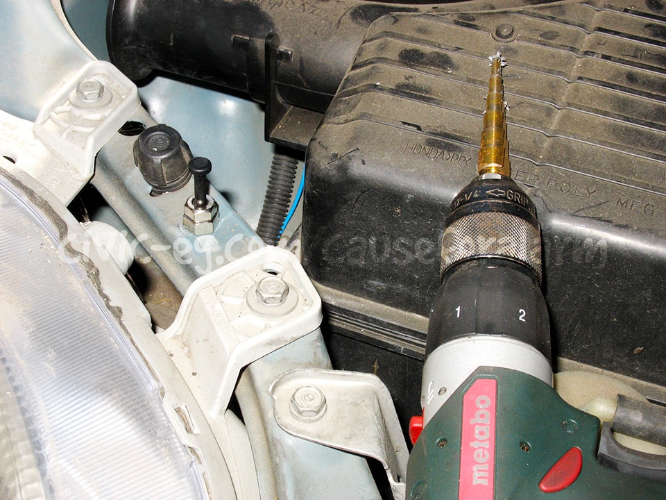
Drill a new hole, making sure there's clearance underneath for when the button is fully pressed. Look for it to be struck by a flat space on the underside of the hood. Be careful when testing not to drop it down hard with the pin fully extended and dent your hood.
Sandwich a star washer between the nut and the sheet metal. Use a ring terminal to ground the hood pin. Connect the trigger wire with a spade, and run this wire to your siren wires. Consider sealing the pin with paint to prevent rust.
Siren
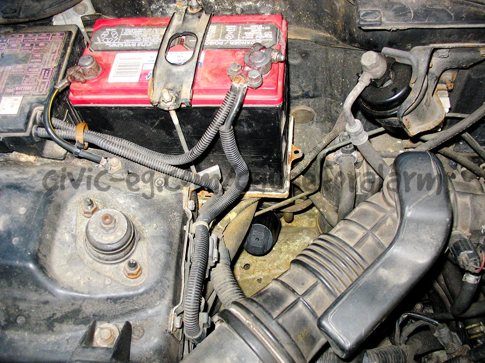
This is an okay location for the siren. Note that it's pointed down so it can't fill with water. Another location is shown in the next photo, see how long it takes you to even notice it.
Tilt Sensor
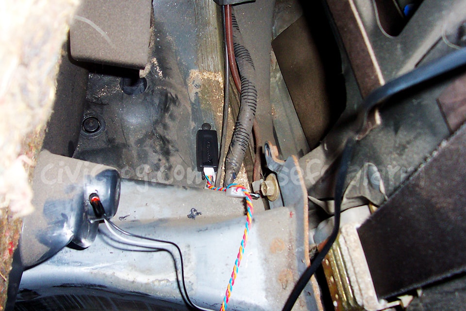
Choose a mounting location very close to the alarm. The sensor harness is short and a pain to extend. Orientation of the sensor is critical. It should be parallel to the ground and secured to the floorpan with a screw. If the screw penetrates to the outside, seal it up with seam sealer, hot glue, paint. I'll leave that up to you.
The Glass Break Sensor comes with a Y harness to plug in an additional sensor, but the plug on it doesn't fit the Tilt Sensor. You have to cut off this plug and splice in your Tilt Sensor's wires.
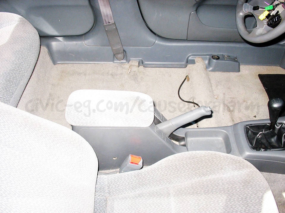
Remove the Interior
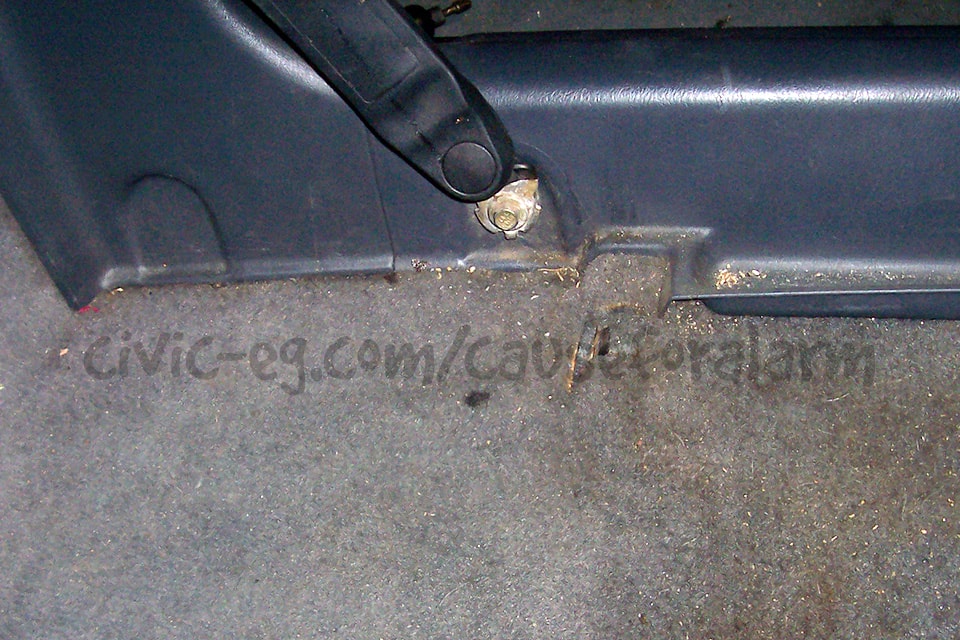
On Civic EK's, you have to remove the front seats to be able to get the door jam plastics off. I recommend doing this on all cars anyway as it is quicker overall and spares you some back pain.
Be careful not to rip out the seat belt warning chime harness on the driver's seat.
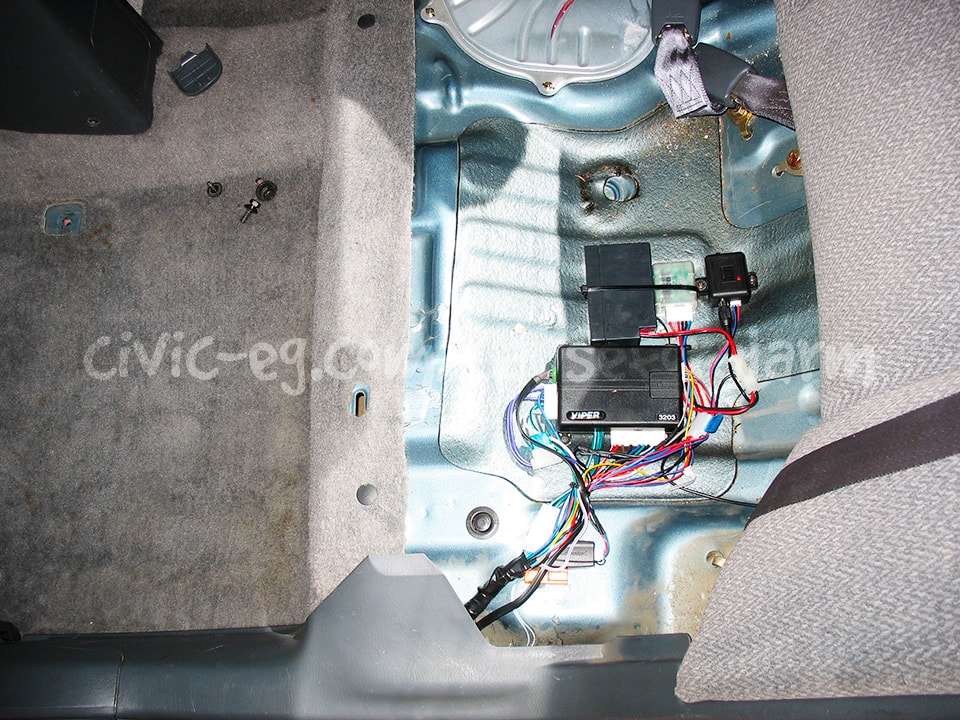
Rear Quarter Panel Install (coupe, hatchback)
Remove Rear Seats
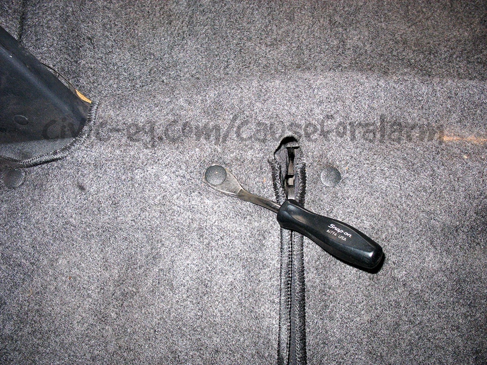
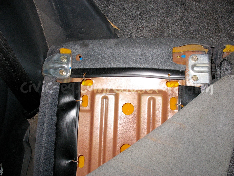
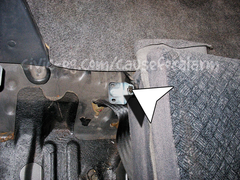
Despite requiring a lot of interior removal, this is by far my favorite place to install the alarm. It's thoroughly concealed, difficult for thieves to get into, and it gives you lots of space to work.
Besides that, I don't consider a used car mine until I've ripped the seats out and cleaned out all traces of previous owners. I've found enough expired driver's licenses, business and credit cards to make a whole deck. Not to mention large piles of change and stale corn nuts to be considered as a rebate on the purchase price.
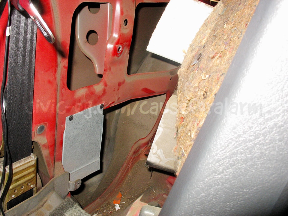
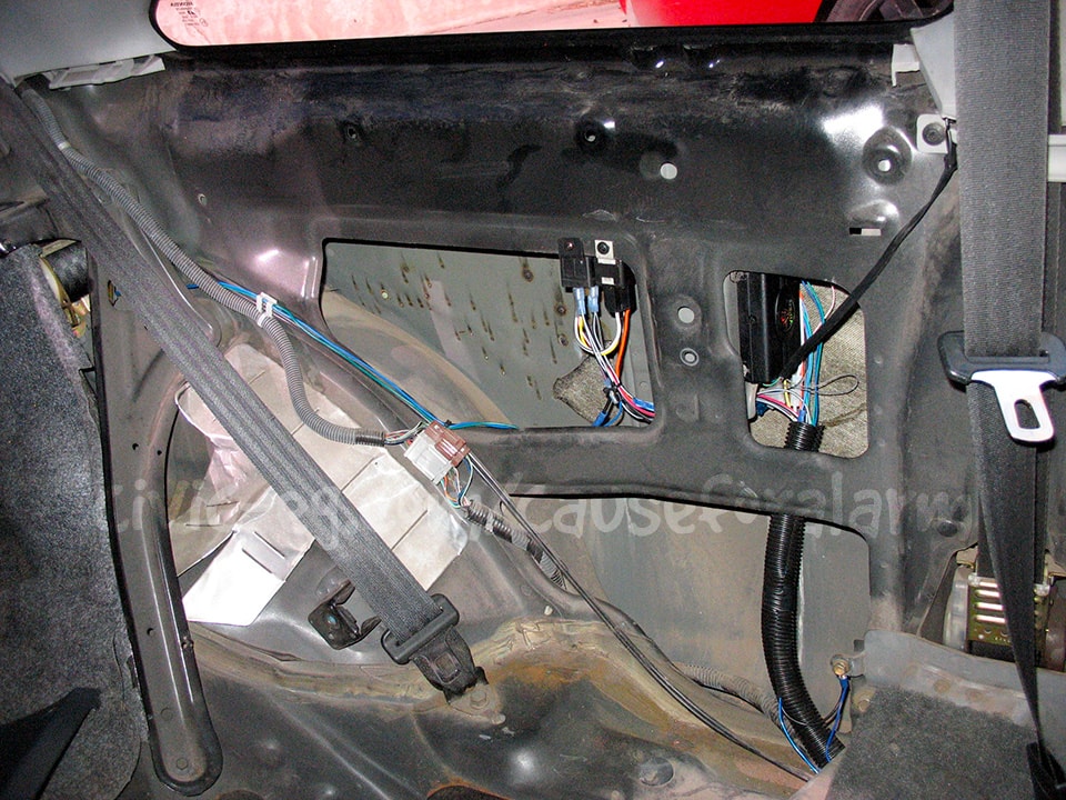
Alarm Connections to the Car
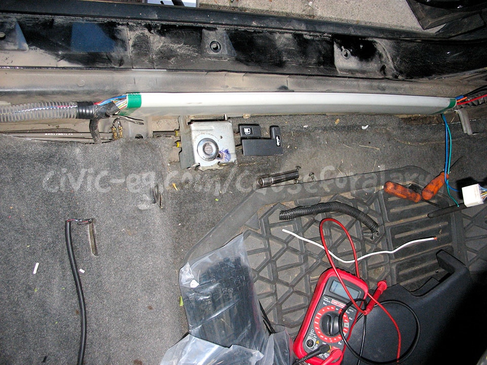
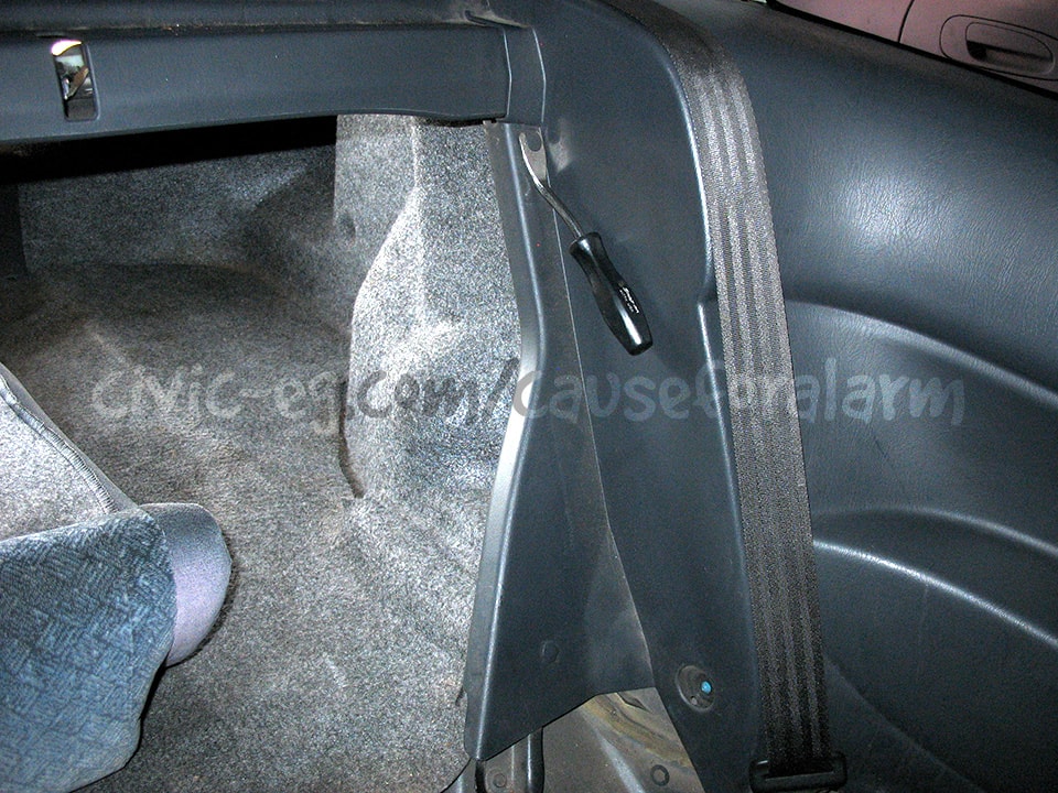
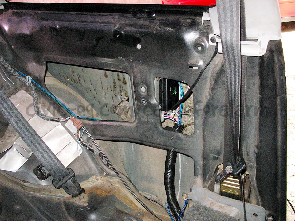
These are the oem wire channels in the door jams. Most of the connections can be found here, and they're ideal for running your alarm wires.
Parking Lights, Constant 12v, and Ignition 12v
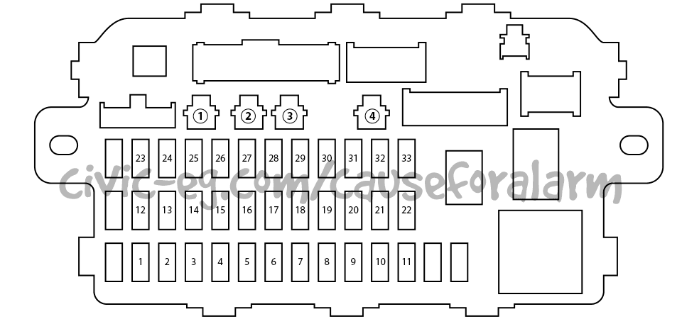
The option output #1 on the under dash fuse box is a Constant 12v. Option output #3 is Parking Lights. Use an option plug connector and an inline fuse holder.
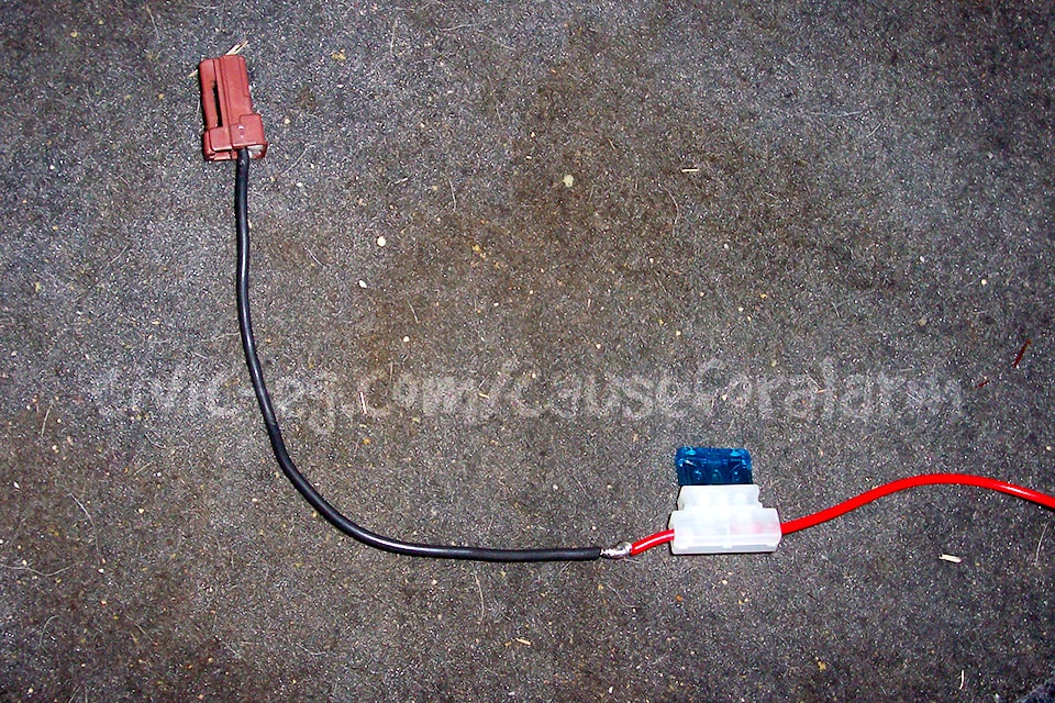
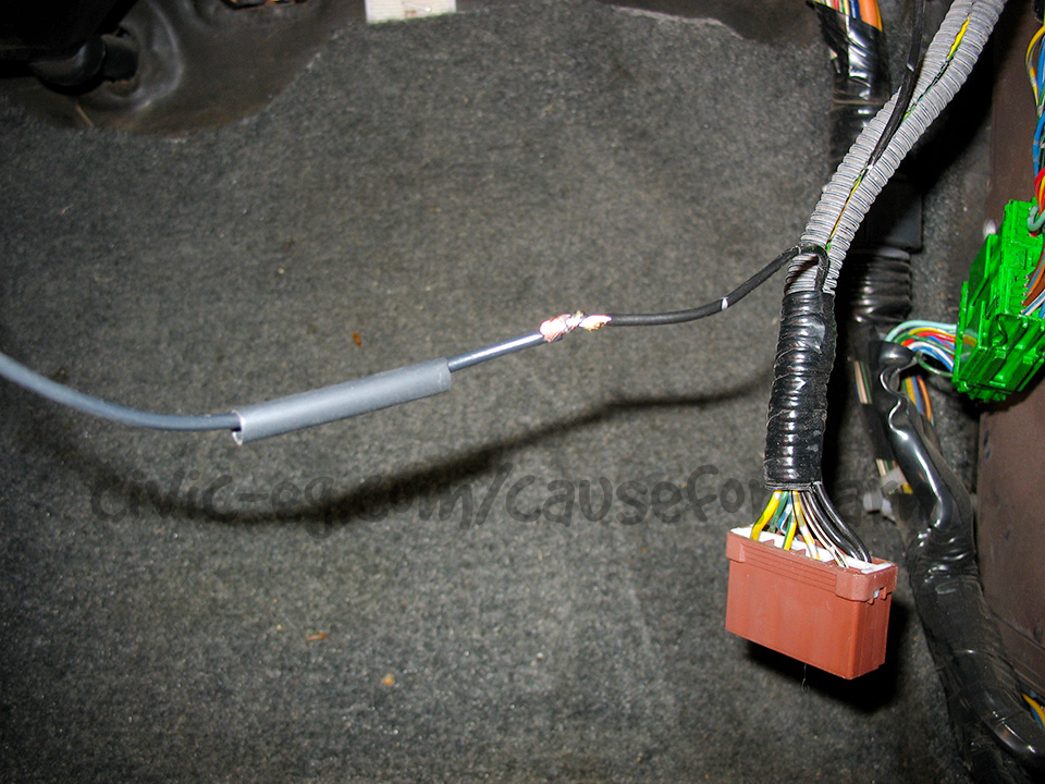
Don't forget to put the heat shrink on before you solder.
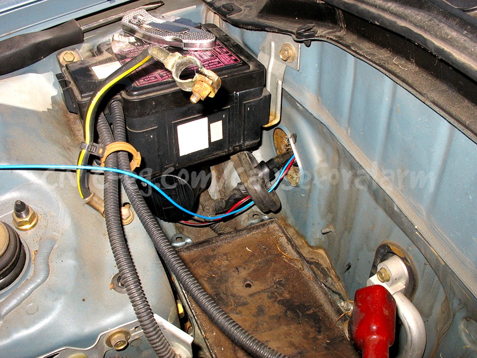
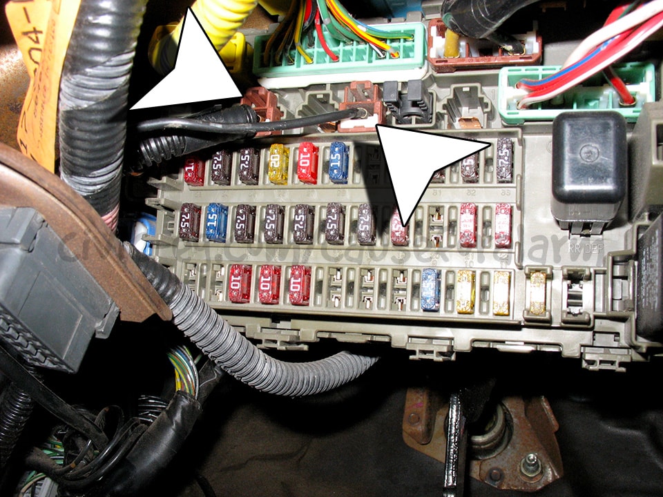
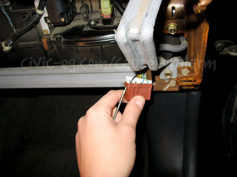
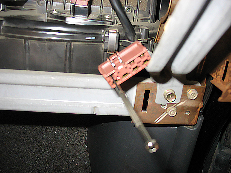
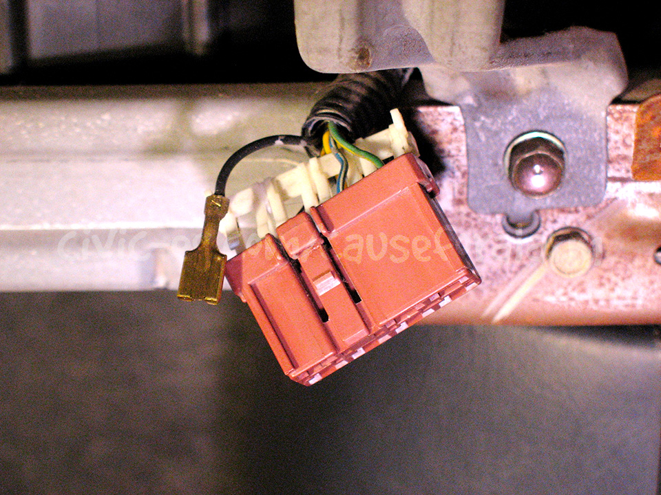
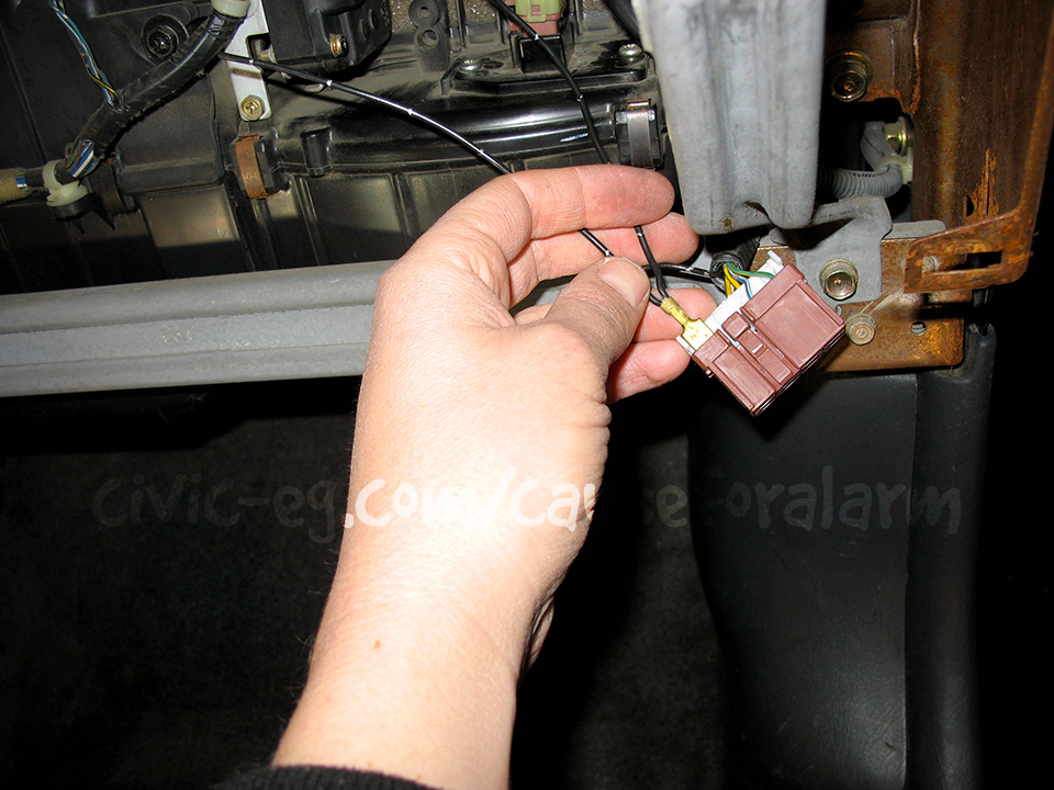
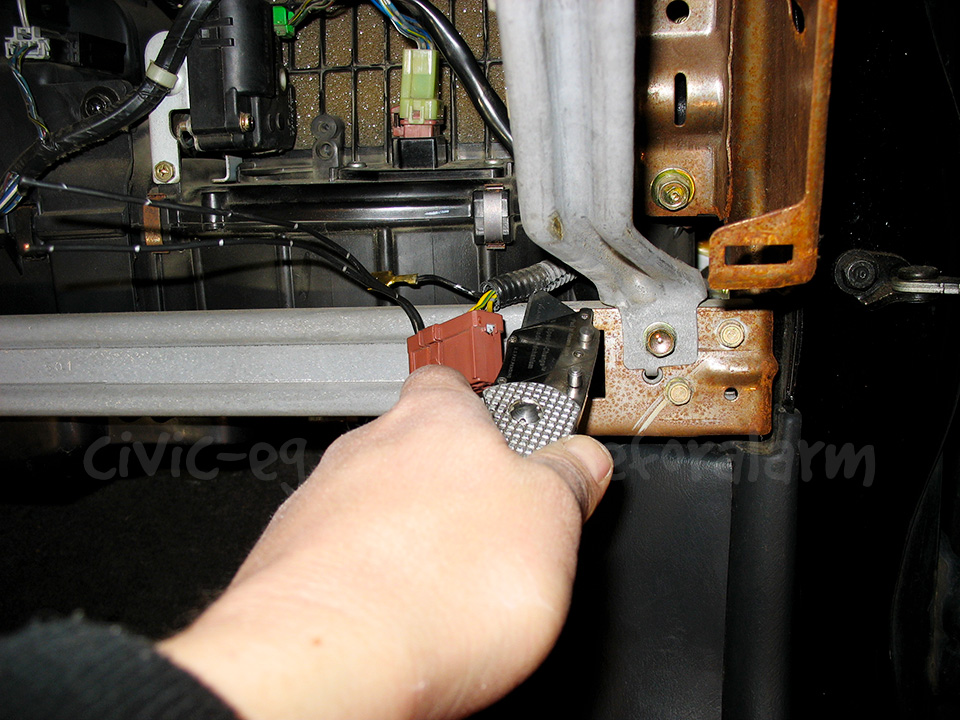
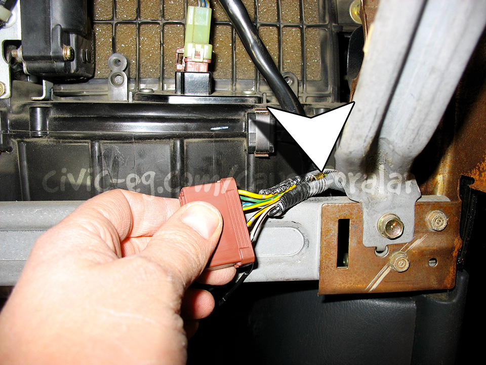
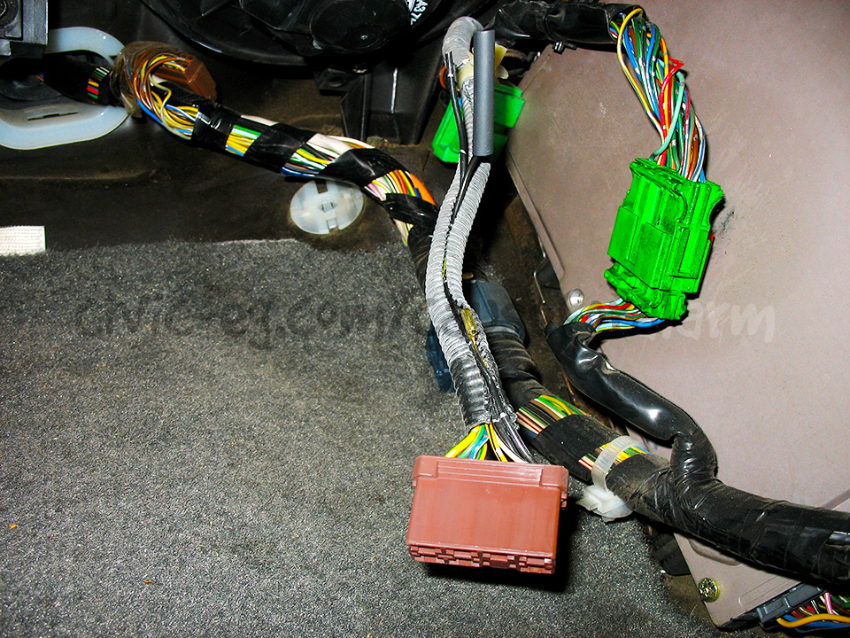
None of the option outputs give provide Ignition 12v, so you have to go to the ignition harness either in this junction connector, or where it plugs into the fuse box (below).
If you're going to conceal the Ignition 12v like this, you could do the Constant 12v this way too (solid white wire). It's up to you.
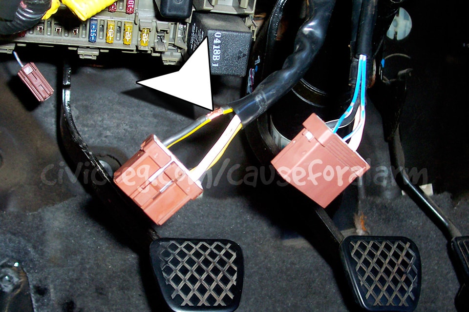
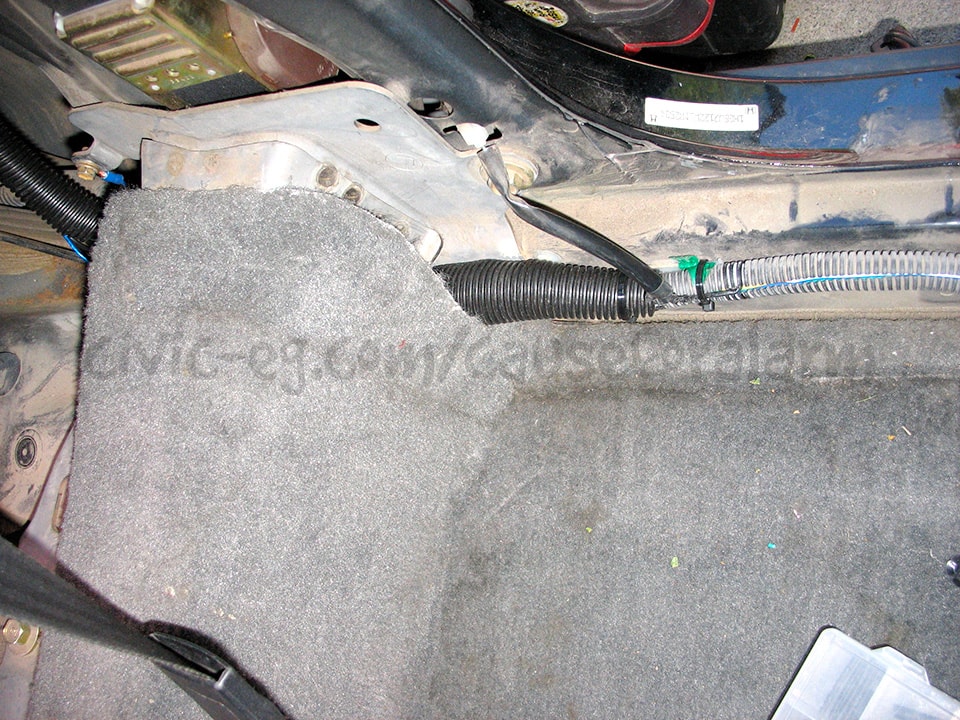
Slide your wire down this OEM sleeve, pull it back, make your connection, then slide it back down.
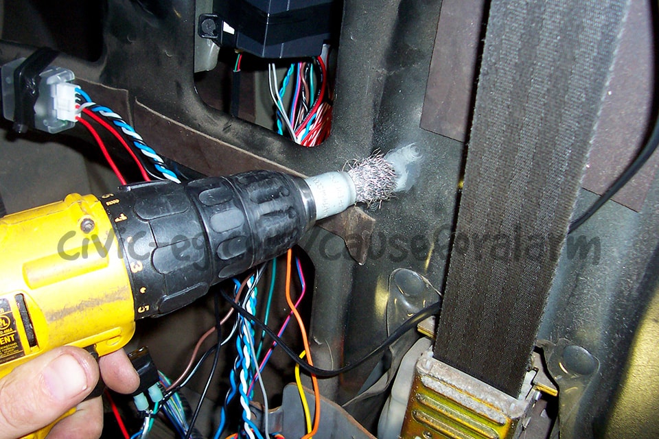
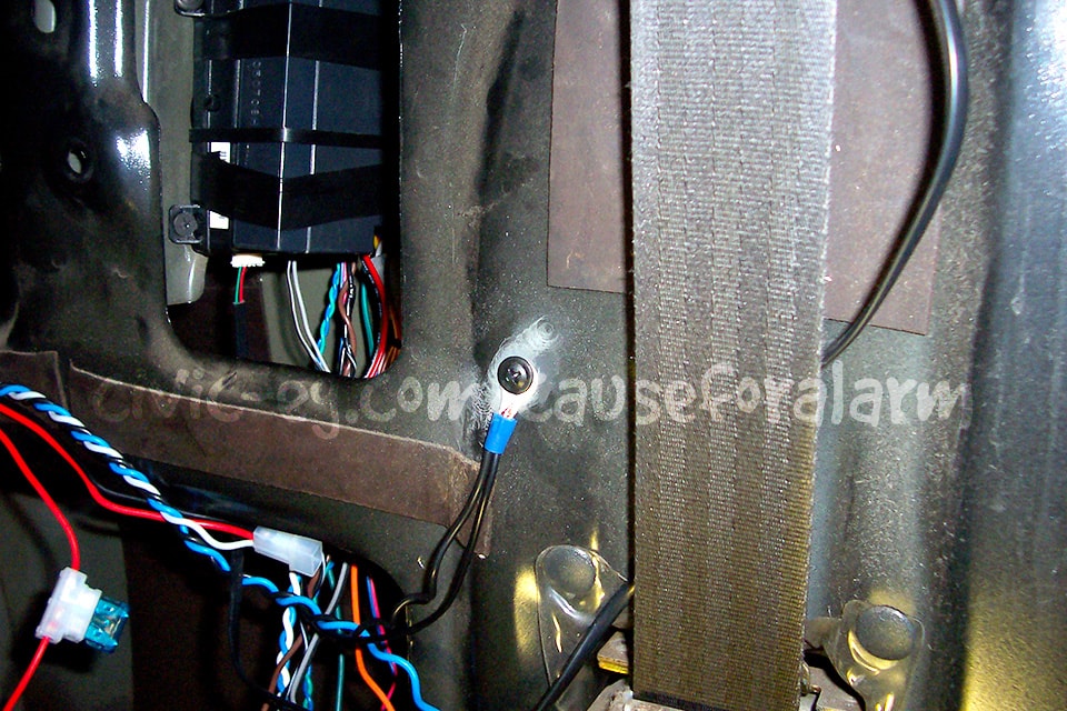
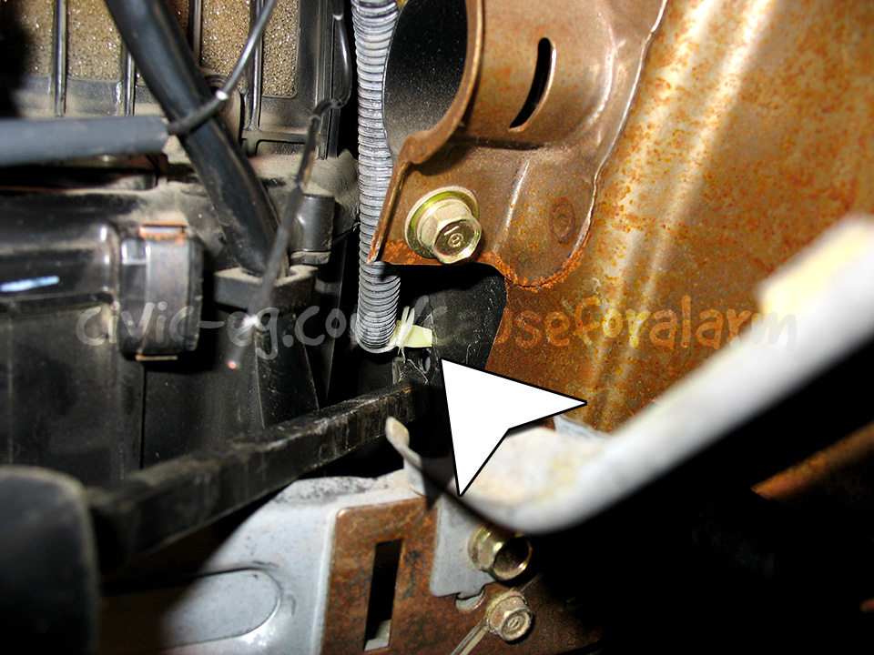
Chassis Ground
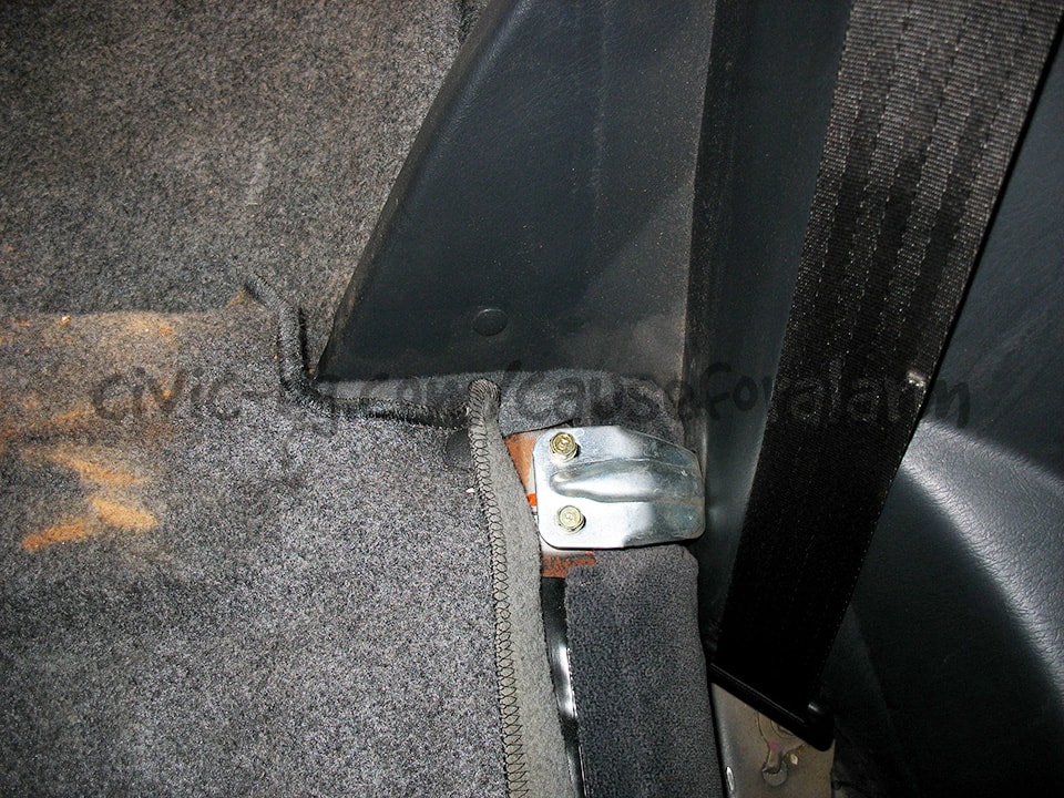
Start Kills
OEM Starter Relay
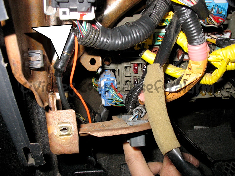
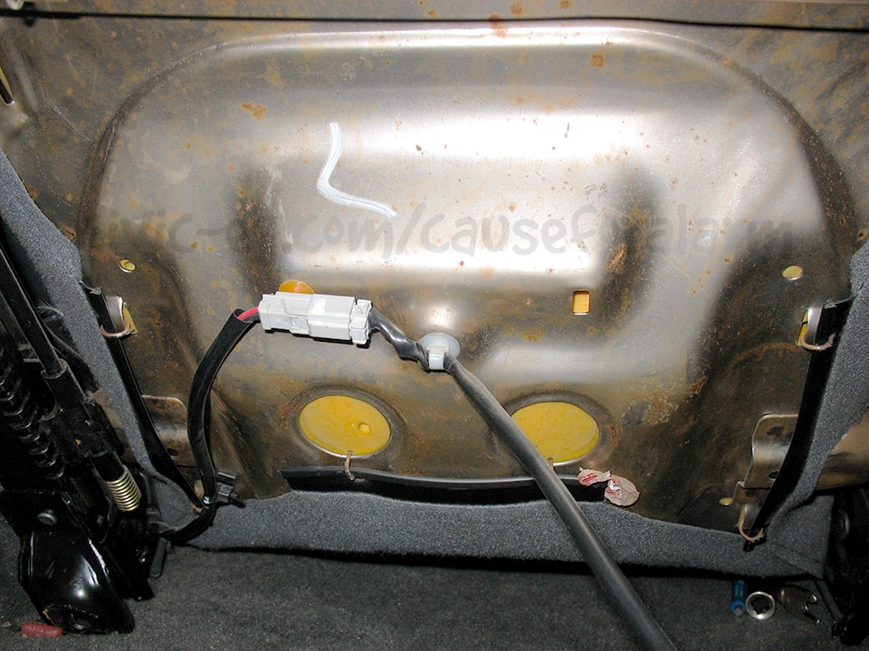
In this instance I ran the alarm's orange ground-when-armed output to the factory starter relay.
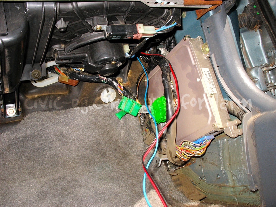
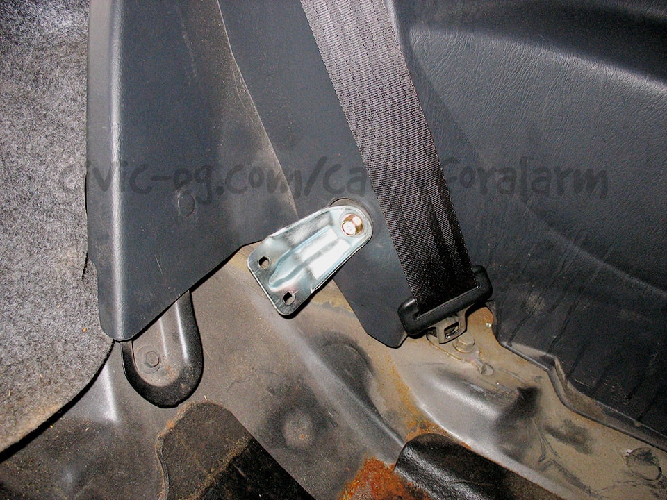
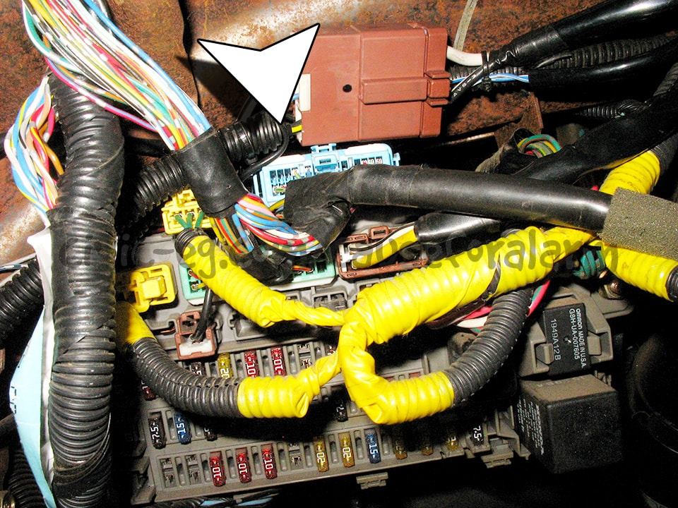
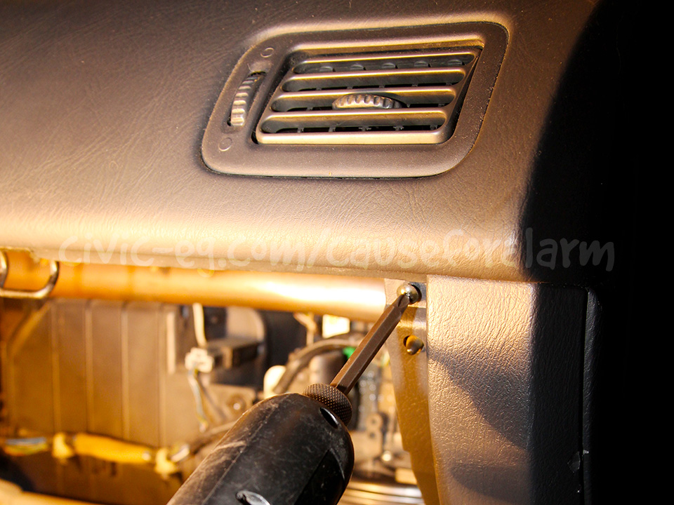
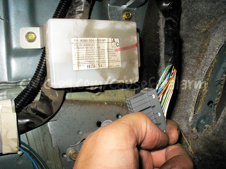
Main Relay
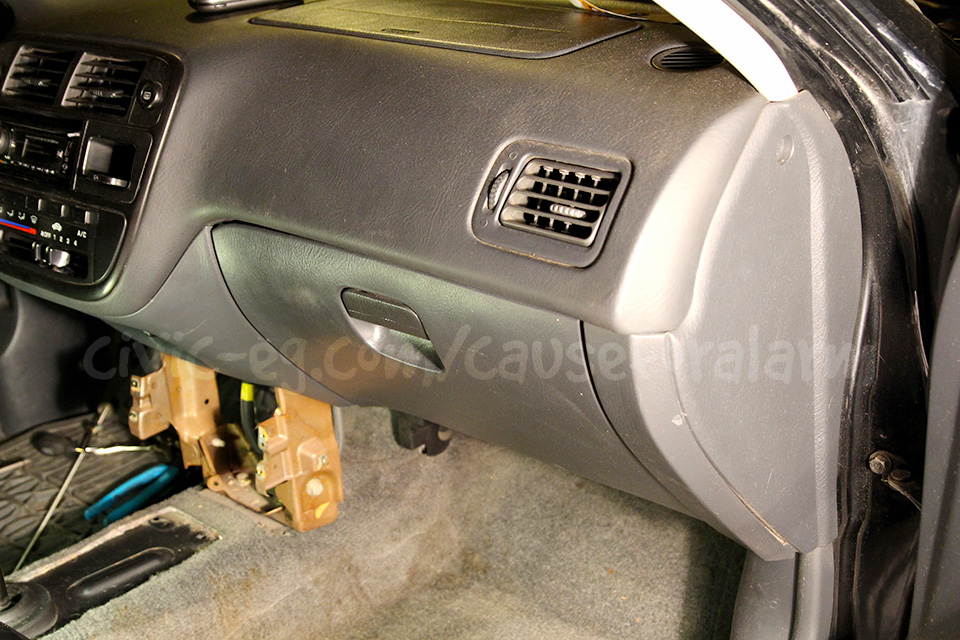

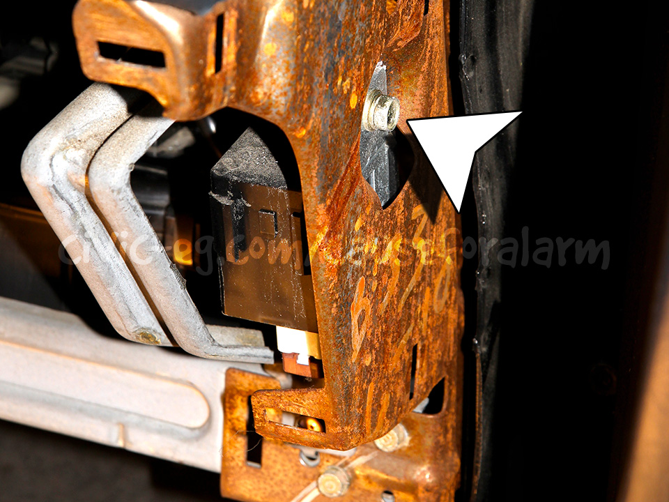
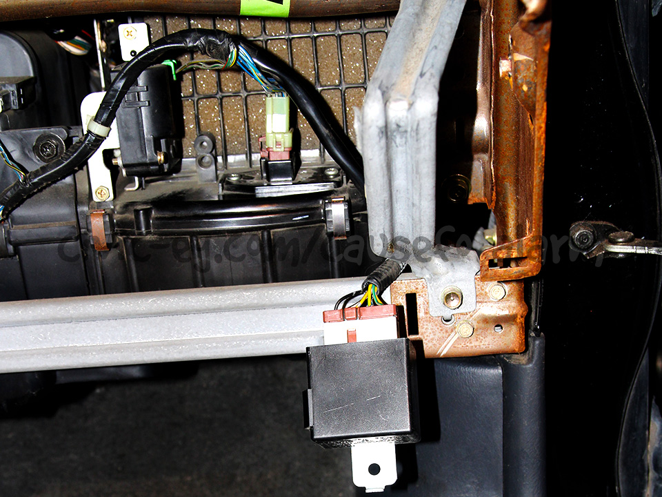
This is optional but I prefer to de-pin my original wire, tuck it away, and insert a junkyard wire in it's place.
If you don't want to do this, you can leave your wire in place and cut it instead.
I prefer to pin junkyard wires and tuck the original wire away.
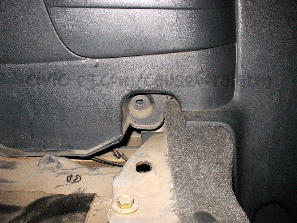
I should have popped out this zip mount right at the start to get easier access to the harness.
It's your choice to run this to a hidden switch to ground or to the start kill relay provided with the alarm. All that's left then is to tape it back up again.
Door Locks
Power Door Locks
If your car came with power door locks and you want the easiest possible install, simply connect the two 22 gauge wires to the oem keyless entry harness under the driver's kick plastic. Verify by tapping the lock or unlock wire to ground.
Onboard Door Lock Relays
Some alarms come with onboard doorlock relays. This is a good thing if you're adding doorlock actuators to a manual lock car. If your car came with power door locks, it's an unfortunate complication.
The wire colors are the same as the 451M module, sometimes with another wire for the built-in "Flex" domelight relay. The domelight flex input (87) should be tied into the main harness ground. If there's also a 87A for the flex relay, just de-pin it.
- Violet - Ground
- Blue/Black - Unlock wire
- Brown/Black - Not Used
- Violet/Black - Ground
- Green/Black - Lock wire
- White/Black - Not Used
- White/Violet - Flex Relay 87 - Ground
- White/Brown - Flex Relay 87A - Not Used
Adding Actuators
If your car came with manual door locks, I HIGHLY recommend swapping in OEM actuators. They bolt right up to your latches. You don't need to change your door panels and get switches and the module. Wire them to the alarm and let it handle the keyless entry.
Any 96-00 Civic actuators will work. You can even put rear sedan actuators in a coupe or hatchback. There's basically just a left and a right side. The driver's door actuator has extra wires but they aren't needed.
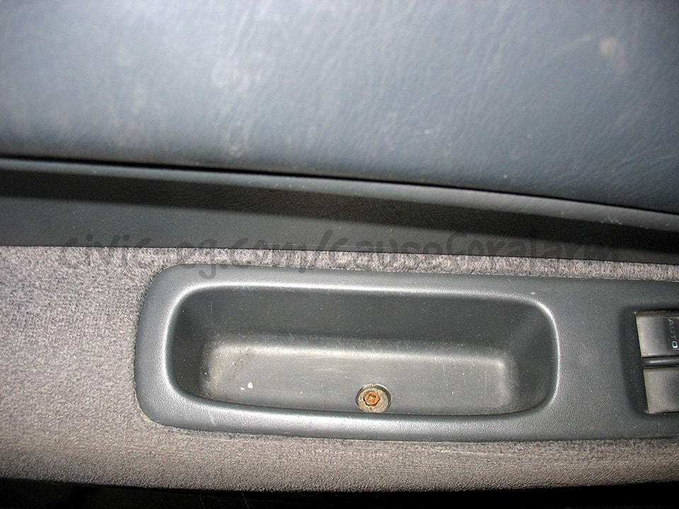
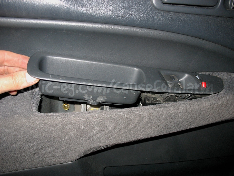
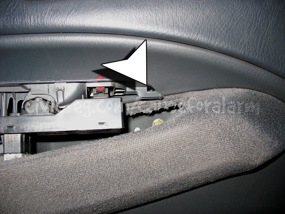
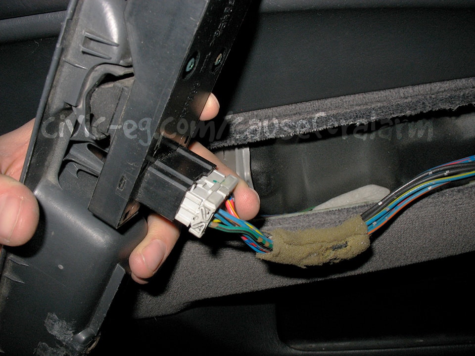
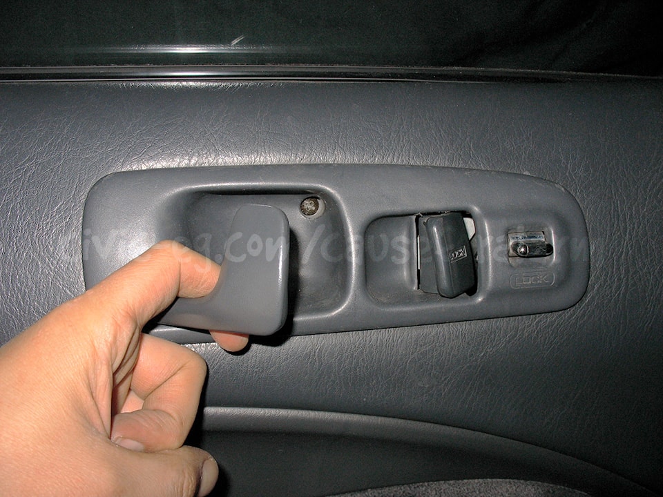
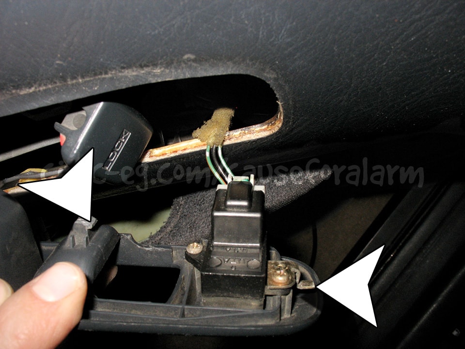
Removing Door Panels
If you're removing the door panels to install actuators, follow these pics to avoid breaking anything.

Actuator Wiring
These are the wire colors for high-end Vipers that have onboard doorlock relays. If you don't want the added expense, you can get a 451M instead. It plugs into your alarm, and the rest of the wire colors are the same as below.
- Violet - Constant 12v
- Blue/Black - Unlock wire on actuator
- Brown/Black - Ground
- Violet/Black - Constant 12v
- Green/Black - Lock wire on actuator
- White/Black - Ground
- White/Violet - Flex Relay 87 - Ground
- White/Brown - Flex Relay 87A - Not Used
Get My Car Alarm Visual Guide! (click me)
Cause For Alarm Patreon supporters get access to my ever-evolving Car Alarm Visual Guide. It's a series of pdfs that cover every possible door lock scenario, including Driver's Priority Unlock (which I strongly recommend to prevent "sliders"), bypassing the OEM door lock module, adding actuators, trunk pop relay etc. It also vastly clarifies the many power and ground wires that all get tied together. How to splice the Tilt Sensor into the Glass Break Sensor's Y harness. How the diodes branch off the trunk trigger wire. Simple examples to get beginners intimately familiar with relays. My guide is unique to anything out there and you wont get it any other way than by supporting me on Patreon.
These are not wiring schematics requiring an electrical engineer. These are clearly designed visual representations of what your wiring will look like. Much better than what I can explain in words and photos. Having them centrally located and in pdf form allows me to rapidly develop and easily update in response to user's questions and feedback.
I spend an incredible amount of time so that you gain a lifelong skill, save hundreds of dollars, and prevent your car from being stolen. Each and every donation results in expanding content. Thank you for showing appreciation!
Trunk Popper (optional)
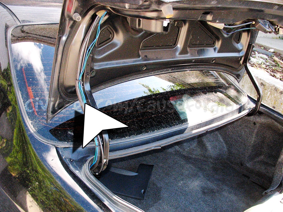
One wire is grounded, the other goes to the 30 output on your Trunk Pop relay (bought separately).
- Trunk Pop Relay Wiring
- 85 to Alarm Red/White aux output
- 86 to Constant 12v Alarm Red
- 87 to Constant 12v Alarm Red
- 30 to Trunk Pop Actuator
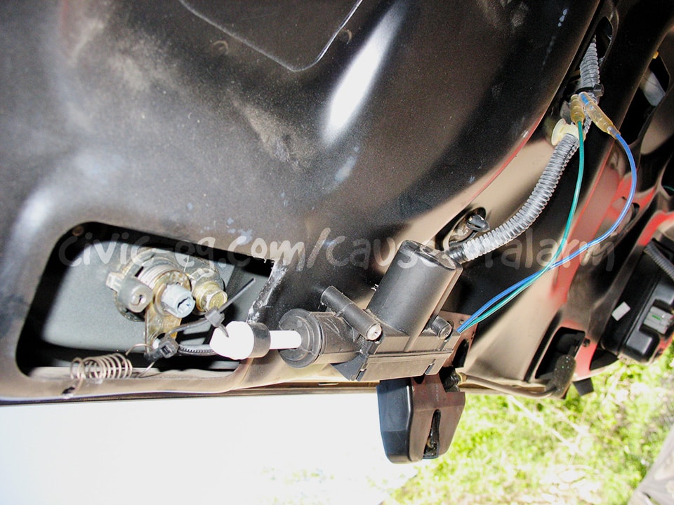
You never use an actual "Trunk Pop Actuator". They are huge and serious overkill. Use a doorlock actuator on the key latch, and fire it in one direction. The recoil resets it back enough in the other direction to work next time, or you can use a spring to help it.
The direction an actuator moves depends on which wire is positive and which is negative (reversing polarity). Depending on how you mount the actuator, you may want it to push or pull.
Getting it all setup correctly can take quite a bit of testing. That can mean climbing into the trunk and triggering the actuator with a 12v battery. In the pic above you can see that I used a spring to pull the latch back after the trunk has been popped. This solved the issue of the trunk bouncing open when you go to close it after having popped it by remote.
Testing the Alarm
Close the doors and trunk and arm the alarm. Make sure both doors lock when armed, unlock when disarmed. Also make sure the parking lights and LED flash. The sirens should chirp. Unlock the door with the key and make sure it triggers the alarm, then test the other door and the trunk. Make sure the car wont start when the alarm is going off, but will start when it's disarmed. Try putting the alarm in valet mode and taking it out (turn the key on but the engine off and tap the valet button).
Program the Valet Button
By default it takes one press on the valet with the ignition on to put the alarm in valet. Program it for 2 or more presses and write it down in the booklet, or just program whatever options you want and then remove the valet button altogether.
Once you are satisfied that the alarm is fully functional, put your interior back together and give it one more quick test.
Troubleshooting Common Mistakes
- Problem: Alarm doesn't respond to remote.
- Solution: Check the alarm's power and ground, power fuse, and that the antenna is plugged in all the way. DEI's paging alarms that don't have remote start have the ability to program a single remote to control four cars. Look for the little number icon. It can be anything from 1-4 but should be set to 1. You can change it by pressing the little blue button on the back of the remote.
- If it's a used alarm, you may need to reprogram the remote to the alarm using the key and the valet button (refer to the manual).
- Problem: Only the driver's door triggers the alarm.
- Solution: You tapped into the driver's side door trigger. The other doors are upstream of this wire. Tap into the passenger-side door trigger instead.
- Problem: Alarm doesn't trigger the door locks.
- Solution: Both the lock and unlock wire must be connected for the door lock system to work.
- Problem: Doors lock on disarm, unlock on arm.
- Solution: You have the lock/unlock output wires reversed.
- Problem: Alarm worked initially, but now it doesn't go off.
- Solution: Cycle the ignition. DEI alarm's have nuisance protection, so if you keep triggering a zone, eventually it will ignore that zone until you have cycled the ignition (turn the key on and off).