
- This Page
- OEM Wire Colors
- Antenna
- LED
- Valet Button
- Hood Pin
- Siren
- Sensor Shock
- Alarm Preparation
- Remove Lower Dash Cover
- Remove the Rear Quarter Plastic
- Mount the Control Unit
- Piezo Siren
- Grounds
- Door Trigger Domelight
- Parking Lights, Trunk Trigger
- Backup Battery
- Diode Isolate Triggers
- Run Wires To Dash
- Fuse Panel Outputs
- Constant 12V
- Ignition 12V
- Starter Kill
- Fuel Kill
- Power Door Locks
- Aftermarket Actuators
- Testing the Alarm
- Program the Valet Button
- Troubleshooting
- Home
- The Basics
- Stealth Installs
- Misc Security
- Kill Switches
- Convenience
- Modifications
- Maintenance
Stealth Car Alarm Install
1994-2001 Acura Integra
The standard type of alarm install you get when you pay a professional to install your alarm just isn't effective. In order for an alarm to be effective, the control unit must be invisible and undetectable, the siren must be hidden and inaccessible, all wiring should be concealed in split loom, the alarm should have its own backup battery, and the alarm must be able to detect all types of intrusion. To accomplish this, you'll need the following:
- Parts
- Alarm (not remote-start) (Recommended: DEI Viper/Python/Clifford/Hornet)
- Battery Backup Module (not siren) DEI 520T
- Piezo siren
- One or two of the following sensors:
- Glass Breakage DEI 506T
- Tilt DEI 507M
You can get sensors and the backup module from ebay, Best Buy, or Circuit City. Alarms you can buy w/out installation at Best Buy or Circuit City. If I mention a particular brand/part number, that means I strongly recommend that exact part. Sensors and backup modules will work with all alarms although they will have to be hardwired in.
OEM Wire Colors
| 1994-01 Acura Integra | ||
|---|---|---|
| WIRE | COLOR | LOCATION |
| 12 VOLT CONSTANT | FAR LEFT OPTION OUTPUT ON FUSE BLOCK | |
| STARTER | BLACK/WHITE | MAIN RELAY |
| IGNITION | BLACK/YELLOW | UNDER DASH FUSE BOX |
| PARKING LIGHTS (+) | RED/BLACK | REAR QUARTER HARNESS |
| TRUNK TRIGGER (-) | GREEN | REAR QUARTER HARNESS |
| DOOR TRIGGER (-) | LIGHT GREEN/RED | DRIVER'S RUNNING BOARD |
| FUEL PUMP (+) | YELLOW/GREEN (THIN) | DRIVER'S RUNNING BOARD |
| POWER LOCK (-) | BLACK/WHITE | DRIVER'S KICK |
| POWER UNLOCK (-) | BLACK/RED | DRIVER'S KICK |
Alarm Peripherals
The best way to start the install is to get all of the alarm's peripherals out of the way. By peripherals I mean both sirens, the antenna, the valet button and LED, all the sensors including the hood pin, and mount the backup battery.
Antenna
Range is critical for two-way paging alarms. For the best possible range, mount the antenna up high and tuck any excess length loosely in the headliner. Never tightly bundle up the wire or range will suffer. Another aspect of antenna range is the strength of the power and ground connections. I'll go over that later.
LED
This customer wanted me to re-use his existing LED in this spot. I used some 22 gauge wire to extend it all the way back to the rear quarter.
If you follow my example and install the LED in the clock panel, be careful to triple check for clearance.
The best mounting place for the LED is a pop out panel that is easily visible from outside the vehicle. Drill a hole using a 17/64 or 1/4 bit. The manual says 9/32, but then the LED will be loose so use the next size smaller and a round file. Press the LED in on a soft surface like a carpeted work bench.
The only bad thing about doing a stealth install is that you'll have to extend the 22 gauge LED, valet, and motion sensor wires. I keep junkyard LEDs available so I can cut off the LED and extend the wires.
Valet Button
You can mount the valet button the same as you would an LED, except you want to hide it. I usually just wait until the install is finished, program whatever options I want, and then remove the valet button. You can put the alarm into valet by hitting lock, unlock, lock quickly in sequence on the remote.
Hood Pin
Hood PinSiren
I removed the intake box to hide the siren underneath. Another good place to hide the siren is below the battery tray.
What Siren?
Sensor (external shock)
If your alarm came with an external shock sensor, and you bought two other sensors like I told you, don't use the shock sensor. It's basically worthless.
Other Sensors
This install only had one sensor and I didn't take any pictures. Just look through all the other write-ups. Between them I've covered every useful kind of sensor.
Alarm Preparation
This is the hand of an overworked installer. My hands no longer look this scratched up. I'm tempted to take a picture of my unemployed left hand just for this page.
De-pin the white/blue if applicable (never used), purple (positive door trigger input doesn't apply to Japanese cars), and red/white (negative aux output used for trunk poppers etc) wires.
Cut the red wire 1 inch before the fuse because we will be connecting this to the backup battery's grey wire. Cut the black/white (negative dome light output) wire at about the same point as the red wire and splice it together with the green (negative door trigger input) wire. I like to keep the alarm's cutting and splicing all at the same level because it's easier to trace down later if there's a problem. Another thing I always do is take the leftover black/white wire and branch off the black wire. Now you can use this extra ground for the siren ground wire. Cut the slack from the yellow and orange wires that go to the start-kill relay. I like to make them the same length as the relay's green and black wires.
If you haven"t noticed yet, alarms have a lot of wires to manage. To help keep them clean and organized, you should twist wires together if they're going the same direction or are connecting to the same point. Put them in the end of your cordless drill, tighten the chuck down, hold the wires tight, and pull the trigger.
This car must have power door locks because in this pic I'm scavenging the fuse holder and the 22 gauge wire harness from this 451M. I use the branched purple and purple/black wires and fuse holder for connecting the sirens. You can use the three pin 22 gauge harness in place of the 2 wire door lock harness so that you have an easy Constant 12V source for an extra sensor.
Getting Serious
Removing Lower Dash
There's a screw hidden behind the coin pocket. Pry it out carefully as shown.
Remove the other screws and pop the lower dash panel off starting at the top.
Use the panel popper to remove the stubborn pop in the driver's kick.
Removing Rear Quarter Plastic
Remove the plastic stops at the far edges of the rear seat-backs, then push a seat-back to the center and remove the seat pivot collar that is between the side of the seat and the quarter plastic. Fold them over and out of the way without crushing the rear carpet. Remove the 10mm at the back of the seat-bottom, then lift up the back and unhook the front two clips.
Remove enough of the screws and bolts so that you can pry the rear quarter out enough to work behind. If this is your first or only install, you may just pull the whole plastic out.
Carefully pry the edge off as shown. Try not to kill your fingers or crease the plastic.
This is where the magic happens. Again, don't be like me. Just remove the whole rear quarter panel cover.
Mount the Control Unit
I forgot to take a good picture of the control unit mounted, but you can get an idea from the top right of this picture. I used some long zip ties through the tabs on the brain.
Wiring
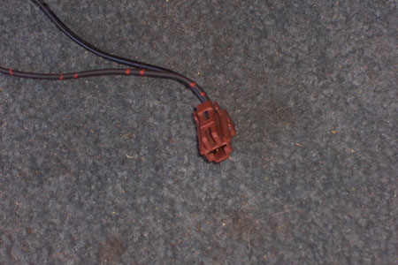
Piezo Siren
Tap into the brown and black/white wires that will be running to the siren under the hood. Put an inline fuse on between the brown wire and the engine bay siren's red wire. That way the thief can't short out your interior siren by cutting your engine bay siren's power wire and grounding it. Use a 1A fuse. If you have power door locks and scavenged the 451M module as I mentioned in Alarm Prep, you can use the purple wires and fuse holder for the sirens. This can be very useful for branching the sirens cleanly. You connect the single wire to the engine bay siren. Either of the wires on the other end of the fuse connects to the alarm's brown siren output, and the remaining wire connects to the piezo's power wire.
Grounds
GroundsDoor Trigger/Domelight
Close all the doors, set your meter to continuity, connect one probe to chassis ground and the other to the suspected wire. There should be no continuity (meter shows 1). Open a door and the meter should drop to 0. Test each door individually.
Parking Lights, Trunk Trigger
Like nearly every other Honda/Acura, the parking light wire is red/black. It can be found in the harness that runs down the door sill, past the quarter panel, and to the tail lights.
The trunk trigger is one of the more difficult wires to locate and confirm, simply because there are many wires that are the same color. The trunk trigger is usually a 18 gauge green wire on this model. Scrape back some insulation and connect one of the probes from your meter. Set the meter to continuity. Ground the other probe. Have a friend pop the trunk manually (and close it again if it's the wrong wire). Your meter should show perfect continuity. This wire often gives me problems. You can confirm the wire color by going to the latch. There will be a pin with a single wire that is very obviously for the trunk trigger.
Backup Battery (DEI 520T)
Leave the module unplugged until the wiring is completed. Tap the blue trigger wire into the blue trunk trigger wire or the grey 22 gauge hood pin input on the remote start alarms. If you're branching off the alarm's blue wire, most likely it will be shared with other sensors (especially the trunk trigger). It's a good idea to isolate the triggers using diodes. The high end alarms come with a pair of diodes in white heat shrink.
The diagram that comes with the DEI 520T is better than any instructions I could ever give. Some people get tripped up on the power connection. Cut the alarm's red power wire an inch before the fuse and connect it to the backup module's grey wire. Then connect the module's red wire to constant 12v coming from the car.
Diode Isolate Trigger Wires
Use diodes to isolate each sensor that you branch onto the alarm's blue instant trigger wire. In this example I had the trunk trigger and the battery backup trigger. You can use 1 or 3 Amp diodes. The striped end faces the sensor.
Run Wires To Dash
Pry open these plastic holders in the running board so that you can run all your alarm wires inside. Use split loom for the sections between the plastic holders. Basically you'll need to run your door lock wires, ignition wire, constant wire, and the ground-when-armed wire if you are doing a second start-kill.
Fuse Panel Outputs
This model Integra, like many other Hondas/Acuras, has extra option power outputs on the under-dash fuse box. You can source option plugs in the doors and engine bays at the junkyard, or you can use female quick disconnects. There are constant 12v outputs, accessory 12v outputs, and a parking light output. Use an inline fuse holder with a rating of 15A (if powering the alarm), 1A if powering relays, or 10A or so if powering the door locks. The lowest fuse rating you can use is the safest, or you can just throw a 15 in there and never give it a second thought.
The two red option outputs are Constant 12v (insert a fuse into #17 for the second from the left constant 12v), the orange is Accessory 12v, and white is a Parking Light input (fuse 19).
Constant 12V
The far left option output on the under dash fuse box is a constant 12v. Use an option plug connector and an inline fuse holder. When the alarm install is finished, insert a fuse with the same rating as what was on the alarm's constant 12v input (should be 10A).
The wire is pulled tight for the picture. Obviously you will be using electric tape and split loom, and tucking it into an oem loom where possible. The large sloppy crimp connector work to the left was not done by me.
Ignition 12V
You can only get a true Ignition 12v from the 10 gauge black/yellow wire at the under-dash fuse box or the ignition harness. The stealthiest way of tapping into it is to de-pin the wire at the plug connector, pry open the pin, crimp and solder your wire to the ignition wire, then re-pin it.
Starter Kills
Starter Relay
In this example I put the alarm's start-kill relay near the oem starter relay where I interrupted the starter wire. I used a factory threaded hole to hold the relay in place. This start-kill should never be relied on by itself. I use it as a secondary measure to misdirect the thief and make the no-start condition harder to diagnose. If they manage to find the relay where I've hidden it, they will be suprised by the second start-kill. If this is not enough to make them give up, it's only because they have your car completely secluded and in that case, there is little that can save your car besides a tracking device.
Fuel Kill
The fuel pump power wire can be found starting at the fuel pump, traveling along the base of the rear seat, and joining the harness that runs down the door sill. It's one of the yellow/green wires. Like all wires in an alarm installation, it must be confirmed with a multimeter. Put the key on and turn the radio off. If it's an aftermarket radio, remove the face. This is to stop you from mistaking the fuel pump for the yellow/green power antenna wire. Strip back the insulation on the suspected wire, connect the red probe to the bare wire, hold the black probe up to a good ground ie the door latch. Turn the key to the ign position. The meter should go from 0 volts to 12 volts, then back to 0. The reading should correspond exactly with the 3 second whirring sound of the pump and the click of the main relay.
Other Start-kills
These are just two possibilities. Please view the Kill Switch page for more alternatives.
Door Locks
If your car has power door locks, you will want to hook up the keyless entry. If your car has manual locks, you can install aftermarket actuators (recommend 2 wire), convert to power door locks, or just not have keyless entry at all.
Power Door Locks
If your car came with factory door locks, you simply have to connect the 22 gauge green and blue wires to them in the driver's kick. Connect the alarm's green negative door lock wire to the car's black/white, and the alarm's blue negative unlock to the car's black/red. If you have problems finding these wires you may have to go directly to the control unit or switch in the driver's door.
Some DEI alarms come with the 451M built into the alarm brain and a 7 pin harness for the door locks. In that case, wire it up as follows (de-pin the wires marked in red):
- H3/A - Black/White to Ground (domelight)
- H3/B - White/Black
- H3/C - Green/Black to Lock wire
- H3/D - Violet/Black to Ground
- H3/E - Brown/Black
- H3/F - Blue/Black to Unlock wire
- H3/G - Violet to Ground
Aftermarket Actuators
Some of DEI's alarms have a seperate door lock harness with 7 wires. (1 is for the domelight so it doesn't really count. Just ground it.) Some come with a seperate 451M double relay pack with a 3 pin plug for the alarm. Both are wired the same way. DEI takes care of the 85's and 86's for you.
- Violet - Constant 12v
- Blue/Black - Unlock wire on actuator
- Brown/Black - Ground
- Violet/Black - Constant 12v
- Green/Black - Lock wire on actuator
- White/Black - Ground
Using Two Relays Instead of the 451M
Testing the Alarm
Close the doors and trunk and arm the alarm. Make sure both doors lock when armed, unlock when disarmed. Also make sure the parking lights and LED flash. Make sure both sirens chirp. Unlock the door with the key and make sure it triggers the alarm, then test the other door and the trunk. Make sure the car wont start when the alarm is going off, but will start when it's disarmed. Try putting the alarm in valet mode and taking it out (turn the key on but the engine off and tap the valet button).
Program the Valet Button
By default it takes one press on the valet with the ignition on to put the alarm in valet. Program it for 2 or more presses and write it down in the booklet, or just program whatever options you want and then remove the valet button altogether.
Once you are satisfied that the alarm is fully functional, put your interior back together and give it one more quick test.
Troubleshooting Common Mistakes
- Problem: Alarm doesn't respond to remote.
- Solution: Check the alarm's power and ground, power fuse, and that the antenna is plugged in all the way. DEI's paging alarms that don't have remote start have the ability to program a single remote to control four cars. Look for the little number icon. It can be anything from 1-4 but should be set to 1. You can change it by pressing the little blue button on the back of the remote.
- If it's a used alarm, you may need to reprogram the remote to the alarm using the key and the valet button (refer to the manual).
- Problem: Only the driver's door triggers the alarm.
- Solution: You tapped into the driver's side door trigger. The other doors are upstream of this wire. Tap into the passenger-side door trigger instead.
- Problem: Alarm doesn't trigger the door locks.
- Solution: Both the lock and unlock wire must be connected for the door lock system to work.
- Problem: Doors lock on disarm, unlock on arm.
- Solution: You have the lock/unlock output wires reversed.
- Problem: Alarm worked initially, but now it doesn't go off.
- Solution: Cycle the ignition. DEI alarm's have nuisance protection, so if you keep triggering a zone, eventually it will ignore that zone until you have cycled the ignition (turn the key on and off).