
- This Page
- Antenna
- LED
- Valet Button
- Piezo Siren
- Engine Bay Siren
- Re-route Hood Cable
- Hood Pin
- Prep Alarm
- Starter Outputs
- Constant 12V
- Ignition / Accessory 12V
- Hide Control Unit
- Remove the Cluster
- Wire Connections
- Cluster Harness
- Parking Lights
- Trunk Trigger
- Tach
- Rear Defrost
- Door Trigger / Domelight
- Neutral Safety Output
- Clutch Switch Bypass
- DEI 520T Battery Backup Module
- Door Locks
- Driver's Priority Unlock
- Trunk Pop
- Fuse Box Outputs
- Additional Start-kills
- Recommended Programming Options
- Test the Alarm
- Home
- The Basics
- Stealth Installs
- Misc Security
- Kill Switches
- Convenience
- Modifications
- Maintenance
Stealth Alarm Install
1992-1995 Honda Civic
This is a Viper 5900 two-way paging alarm, remote start, keyless entry install behind the gauge cluster in a fifth generation Civic. Any DEI alarm going into any model 92-95 Civic or 94-01 Integra will be very similar, and I will keep the terms general enough to make this useful for any brand alarm. Cluster installs are recommended for stealth remote starts or stealth installs into sedans or cars with a stripped interior. Do not attempt to install an alarm behind the cluster on a 91 or earlier Civic, 96 or later Civic, or 93 or earlier Integra. There simply isn't room and you're likely to break something on the older cars with the cable speedometers.
This install is not easy. It took me two days and I've been installing alarms for years. If you're not doing remote start, and your car has two doors, I strongly suggest you do my more common stealth install underneath the driver's side rear quarter plastic. Look at the other installs for a rear quarter panel install.
This page is intended to supplement the instruction manual provided with the alarm.
All wires must be verified with a multimeter. I cover how to do that, as well as what tools and supplies you need, how to make wire connections, and some other things you need to know to install an alarm correctly in "the Basics" section.
Remote Start on a Manual Transmission
When installed correctly, remote start is safe on an automatic transmission. The alarm wont remote start unless the transmission is in park or neutral, so you don't have to worry about the car driving off or lurching. The Viper 5900 is not intended to be installed on manual transmission equipped vehicles. Recently the Viper 5701 was released for that application. It works by requiring you to engage the remote start and exit the vehicle while the engine is running (turbo timer). The alarm shuts down the engine when you close the door.
A manual transmission is different than an automatic in that there is no way to tell what position the shifter is in. There is a start-kill controlled by a switch on the clutch pedal ensuring that the vehicle will not start unless the clutch is pressed in. Installing a remote start requires you to bypass this switch making the car unsafe. I have witnessed remote starts starting spontaneously with no input on the remote. The parking brake, even if properly adjusted and maintained (which often times it is not) is not enough to hold the car in place. Regardless, people are stupid and they will risk life and property in exchange for convenience and admiration. If you want to shortcut portions of this guide to do so, please feel free to send me pics of the resulting disaster.
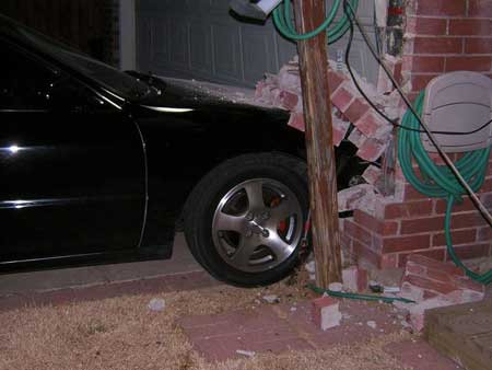
Not my doing.
Alarm Peripherals
Installing an alarm is very complicated; particularly a remote start with all the add-ons. You have to be organized and methodical or else the entire install will be a mess. The best way to start is to get all the "peripherals" out of the way and run their wires to where you will be mounting the alarm brain. By "peripherals" I mean all the sensors, sirens, actuators, the antenna, LED and valet button.
Antenna
For optimal range, run the antenna wire up high and stretch it out completely. I ran the antenna wire up the A pillar and down the headliner until I ran out of slack above the rear quarter glass. This is a good spot for the antenna because it doesn't have defrost lines like the rear glass and it isn't covered by sheet metal (if you were to put the antenna under the headliner).
I've never had a problem with an antenna not sticking to the glass but if you want to be absolutely sure, clean a small area of the glass with rubbing alcohol and heat up the adhesive with a heat gun for a few seconds until it's tacky. Then push the antenna down and hold it in place for 30 seconds. Make sure after you've run the wire and put the plastic trim back in place that the harness doesn't come loose from the antenna.
The manual claims you can get even better range by turning off code hopping in the program menu, but I don't see much of a point.
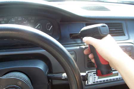
LED
You can drill a hole through the clock-delete or a blank pop out panel for the LED.
I wasn't happy with the outcome so I decided to try something else.
I took out the LED by prying out the cover.
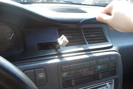
I got another clock-delete panel from the junkyard.
Hot glue the underside to hold the LED in place. Note that the LED will still blink bright blue even w/out the blue cover.
Valet
Generally I do not mount the valet button. I have it plugged in until the entire install is done so that I can program certain options, and then I unplug it before I put the interior back together. If you plan to keep the valet button plugged in, make sure to program the button presses needed to disable the alarm to anything other than the one-press default.
Piezo Siren
This is a pretty decent spot to hide the piezo behind the glovebox, but there are many other possibilities as well.
Engine Bay Siren
One place you can hide the engine bay siren is behind the turn signal in the fender. It's also a good opportunity to relocate the hood cable, but we'll get to that later.
Remove the screw.
Pull the turn signal toward the front of the vehicle. There's a tab on the inside against the headlight and these two tabs on the back. don't break any of these or you will hate yourself for years to come.
Mount it with metal tapping screws (be wary of what's on the engine bay side ie the headlight harness) from the inside or screws and speed clips from the outside.
I ran the wire where the hood release cable used to be, re-using its clips, and in through the hole to the driver's dash.
Customize Siren TonesRe-route the Hood Cable
The problem with the hood cable is that a thief can easily cut the plastic inner fender liner and get to it to pop the hood. Re-route it through the engine bay and make it that much harder for them to get into your car.
Disconnect the cable from the handle, pull it through the fender, pop the clips out, then pull it through the turn signal cavity.
Now re-route it up and over the shock toward toward the master cylinder. Secure it with zipties. Pop out the plastic grommet and run it through, then connect it back to the handle.
Hood Pin
I like to re-use this existing hole for the hood pin because it's easy to access once you've removed the turn signal. Hood pins don't work so well in wet climates because they rust quickly. If you live in a wet climate, I suggest making a mount out of a backstrap so that the hood pin is sheltered under the hood.
Shock Sensor
I never use shock sensors because they're worthless. They don't detect glass breaking reliably. All they do is false alarm. I throw them away and that frees up a sensor port for something else.
Prep Alarm
This is an interconnect harness that I got from Crutchfield. This will allow me to leave my stock wiring stock and uncut, and also looks very stealth when your wires have been tapped in and then covered with split loom and electric tape.
Starter Outputs
I removed the starter kill relay that came attached to the interconnect harness as I will not be using it. The female side of the harness (red wire) is the key side that connects to the green starter output wire on the alarm. The alarm's purple wire goes to the white wire. This harness also has a fused constant 12v connection that can be used for the alarm's power and/or the relays that control the domelight and door locks.
Constant 12V
Strip back an inch of insulation from the thick white wire and solder the two 10 gauge red wires and the red/white wire to it. Then tape up and split loom the whole thing to make it look factory.
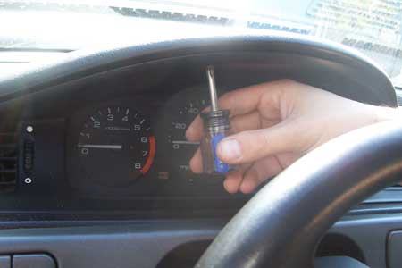
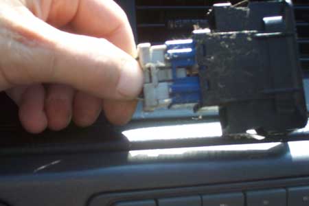
De-pin the 2nd Ignition Wire
The pink/white 2nd ignition output on the relay satellite is not used in our application so it should be de-pinned. Remove the two screws in the plastic cover and then heat up the solder on the circuit board while pulling on the wire.
Twist the ribbon cable so it can be split loomed.
Hide the Control Unit
Remove the Cluster
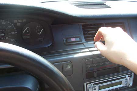
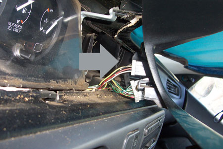
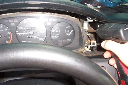
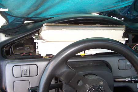
Installing the alarm behind the cluster is a real pain. It's hard to get the control unit into the little cavity, and you'll have to manage all the wiring and peripherals so that the cluster fits nicely into place afterwards. First pop the tab that holds the cluster harness down and then cut the little plastic strap to open up the hole.
Wire Connections
| 1992-1995 HONDA CIVIC | |||
|---|---|---|---|
| WIRE | COLOR | LOCATION | ALARM COLOR |
| 12 VOLT CONSTANT | WHITE | BROWN PLUG ABOVE FUSE BOX OR OPTION OUTPUT | 10 GAUGE RED & RED/WHITE, 18 GAUGE RED |
| STARTER | BLACK / WHITE | BROWN PLUG ABOVE FUSE BOX | PURPLE AND GREEN |
| IGNITION | BLACK/YELLOW | BROWN PLUG ON FUSE BOX | PINK |
| ACCESSORY | YELLOW | BROWN PLUG ON FUSE BOX | ORANGE |
| DOOR TRIGGER (-) | DARK GREEN/RED | A PILLAR | GREEN H1/8 |
| PARKING LIGHTS (+) | RED/BLACK | CLUSTER HARNESS | WHITE H1/11 |
| TRUNK TRIGGER (-) | GREEN | CLUSTER HARNESS | BLUE |
| TACH | BLUE | CLUSTER HARNESS | VIOLET/WHITE H3/2 |
| PARKING BRAKE | GREEN/RED | CLUSTER HARNESS OR PARKING BRAKE SWITCH | |
| FUEL PUMP (+) | YELLOW/GREEN | DRIVER'S RUNNING BOARD | N/A |
| POWER LOCK (-) | GREEN/WHITE | DRIVER'S KICK 2 PIN PLUG | 22 GAUGE GREEN |
| POWER UNLOCK (-) | GREEN/RED | DRIVER'S KICK 2 PIN PLUG | 22 GAUGE LIGHT BLUE |
| BRAKE | GREEN/WHITE | BRAKE SWITCH | BROWN H3/3 |
| REAR DEFROSTER (RELAY) | BLUE/YELLOW | DEFROST SWITCH | BLUE/WHITE H3/5 |
| CLUTCH | BLUE/BLACK | CLUTCH SWITCH | 22 GAUGE BLUE (SATELLITE RELAY) |
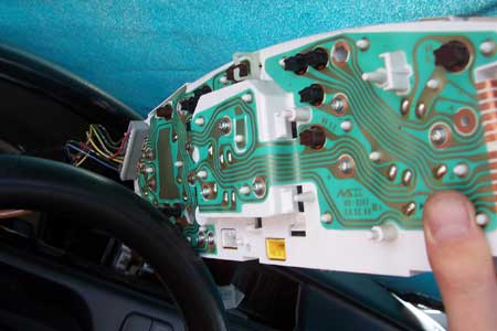
Cluster Harness
It makes no sense at all to put the alarm control unit behind the cluster if you're going to make all your connections in the usual accessible spots under the dash. All the wiring gives away the control units location, but worst of all, a thief never has to get to the control unit if he can get to some of the critical wires. Lucky for you, I found most of the connections on the cluster harness and nearby.
Parking Lights
Connect the alarm's white parking light input to the only red/black wire on the cluster harness.
Trunk Trigger
The trunk trigger is a little more complicated if you're going to be sharing it with other triggers ie the battery backup. This alarm comes with a shrink wrapped set of diodes (the white wires Y'd together with the black shrink wrap.) Connect the alarm's blue wire to the single side of the diode, then connect the branch to the only solid green wire on the cluster harness. Connect the other branch to the battery backup module's blue wire while you're at it. You can add more diodes for more triggers. Get some 1, 3, or 5A diodes and connect the striped end to the trigger side and the solid end to the alarm side.
Tach
Connect the alarm's violet/white tach input to the only solid blue wire in the cluster harness.
Ignition / Accessory 12V
The black/yellow Ignition and yellow Accessory wire can both be found on a brown plug on the under dash fuse box. Take extra care to make the alarm's connection to these wires look factory by using heat shrink or split loom.
Rear Defrost
Remote start alarm's have a 22 gauge blue/white status output that can be programmed to latched for a rear defogger (menu 3, feature 11). its output is listed in mA, so a relay will have to be used. Luckily, you can tap into the wire that triggers the factory relay. It's the blue/yellow at defrost switch. When the car is remote started below 55 degrees it will turn on the rear defrost for you.
Door Trigger / Domelight
Unfortunately on this alarm the black/white domelight output wire is listed in mA, which means it's only strong enough to trigger a relay and not the light directly. So it's up to you whether hooking up the domelight is worth the extra hassle to wire in a relay. Basically the alarm will turn on the domelight for 30 seconds when you disarm the alarm.
Get an auto SPST or SPDT relay and some female quick disconnects (speaker connectors). Connect the black/white to 86, connect 85 to a constant 12v like the option output on the fusebox (explained later). Ground 87 to the chassis with a ring terminal, and branch 30 to the alarm's green door trigger input wire.
Use a panel popper and carefully pop out the grey A pillar trim. Connect the alarm's green door trigger input to the dark green/red wire. This wire triggers when either door opens.
Neutral Safety Input
Automatic Transmission
If you're installing this on an automatic, then connect the alarm's H3/1 blk/wh neutral safety wire to the green wire on the plug harness for the shift position indicator lights behind the cluster. This wire shows ground in both the park and neutral positions. You have the option of putting a toggle switch (provided) inline with this wire so that you can manually lock out remote start.
Manual Transmission
When it's my car on the line, and possibly someone's life or a big lawsuit, this is what my standard of safety looks like. First, a manual LED toggle switch so I can lock out any possibility of unintentional remote start. Also great if I allow someone to borrow the car. A magnet switch mounted to the shifter that is closed only when it's in neutral, and finally it's grounded through the parking brake switch. This also helps ensure that the car wont be parked in neutral w/ the parking brake down. The LED I like to connect to the radio constant (white/blue) since it's nearby. Use a 1 AMP inline fuse. don't forget that the radio memory shares the same circuit as the ECU memory (7.5A fuse under hood). It's a good idea to find two sides of a 3-pin plug at the junkyard to use for the switch so you can unplug it and remove the console when you need to without leaving any bare wires disconnected.
Clutch Switch Bypass
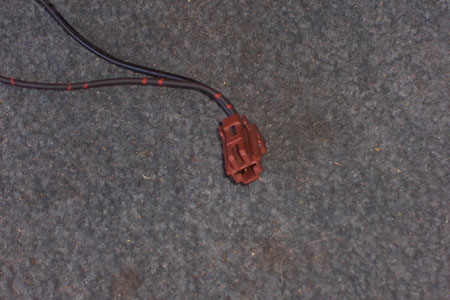
The car has a built in start-kill that wont allow the engine to start unless the clutch pedal is pushed down. We want the alarm to be able to start the car w/out losing oem functionality. The alarm provides a negative 'status" output during remote start. Since we"re using the H3/5 blue/white wire for the rear defogger, we'll have to use the blue wire on the harness that plugs into the relay satellite. Connect it to the blue/black wire on the upper clutch pedal switch with the yellow plug.
DEI 520T Battery Backup Module
Mounting the control module and the battery is not easy. You'll have to get creative with some backstraps, double sided tape, and some zip ties.
Connect the red wire to a constant 12v source like the wire coming out of the interconnect harness.
Cut the alarm's red wire before the fuse and connect it to the battery backup's grey wire.
Branch the battery backup module's blue wire to the alarm's blue trigger input via a diode as I explained earlier.
Ground the black wire via a ring terminal to the chassis.
Fuse box Outputs
Many Hondas/Acuras have extra option power outputs on the under dash fuse box. You can source option plugs in the doors and engine bays at the junkyard, or you can use female quick disconnects. There are constant 12v outputs, accessory 12v outputs, and a parking light output. In this install we are only concerned with the far left constant 12v. Use an inline fuse holder with a rating of 15A (if powering the alarm), 1A if powering relays, or 10A or so if powering the door locks. The lowest fuse rating you can use is the safest, or you can just throw a 15 in there and never give it a second thought.
The two red option outputs are Constant 12v (insert a fuse into #17 for the second from the left constant 12v), the oranges are Accessory 12v (insert a fuse into #16 for the center option output), and white is a Parking Light input (fuse 19).
Power Door Locks
If your car came with factory door locks, connect the 22 gauge green and blue alarm wires to them in the driver's kick. The green negative door lock wire goes to the car's green/white, and the blue negative unlock wire goes to the car's green/red. They're on a two-pin plug that isn't plugged into anything (optional security system), taped with blue tape to the harness coming from the driver's door behind the hood release cable that goes up behind the fuse box. Cut off the plug and wire them up directly.
Aftermarket Actuators
I cover how to install and wire actuators in the "actuators" section. Use the 451M relay pack included with the alarm and wire it as follows:
- White/Black to Ground
- Green/Black to Lock wire
- Violet/Black to Constant 12v
- Brown/Black to Ground
- Blue/Black to Unlock wire
- Violet to Constant 12v
Driver's Priority Unlock
This alarm has a "2nd unlock output" (requires an additional relay) giving you the option of driver's priority unlock. A lot of newer cars have this feature. What it means is that only the driver's door unlocks when you disarm the alarm or turn off the ignition. If you want the passenger's door to unlock, you have to hit disarm a second time.
Instead of connecting the passenger side actuator's unlock wire to the 451M like the driver's side, you hook it up to its own relay that's controlled by the alarm's 2nd Unlock Output (H2/1 light blue).
Recommended Programming Options
You program these options using the key and valet button as per the installation manual (p 40). I list the options that should be changed from the default settings.
- Menu 1, Feature 1: Passive Arming ON *
- Menu 1, Feature 9: Automatic Engine Disable ON
- Menu 2, Feature 4: Change to anything other than the default
- Menu 3, Feature 11: Rear Defogger latch 10 min
*alarm will arm itself automatically if you forget to, but not lock the doors so you don't accidentally lock your keys inside the car.
also don't forget to learn the tach (p 32)
Test First, then Reassemble
- Make sure each door, the hood, and the trunk set off the alarm.
- Make sure the doors lock on arm and unlock on disarm.
- Make sure the doors lock on ignition and unlock when you remove the key.
- Make sure the parking lights flash and both sirens chirp on arm and disarm.
- Make sure the domelight is controlled by the alarm.
- Sit inside the car and test the remote start. Make sure it shuts down with the brake.
- Make sure the remote start wont start with the hood open, parking brake down, or shifter in gear.
This is the last pic I took. Not beautiful, but organized and clean. All the wires are secured to the factory loom w/ zip ties so that the cluster drops right in. Most of these wires don't need to be concealed because the dash cover and sheet metal takes care of that for you. Any wires visible from below are split loomed and then taped.
Alarm Features (in this install)
- Multiple Start-kills
- Battery Backup (Trigger)
- Hood Trigger
- Door Trigger
- Trunk Trigger
- Tilt Sensor
- Motion/Proximity Sensor
- Two Way Paging
- Remote Start (MT Safe)
- Defrost
- (Keyelss Entry) Door Lock Actuators
- Trunk Pop (Actuator)
- Domelight Supervision
- Parking Light Flash
- Ignition Controlled Door Locks
- driver's Priority Unlock
Harness Preparation:
Viper 5900 & 791XV
Python 990 & 881XP
Clifford Matrix 50.5X & RSX3.5
This is a quick breakdown of how each wire will be used and which will be de-pinned.
You can de-pin the following marked in red.
- H1/1 - Red/White (optional trunk pop)
- H1/2 - Red to Constant 12v
- H1/3 - Brown to Siren Red
- H1/4 - Empty
- H1/5 - Black to Chassis Ground
- H1/6 - Violet
- H1/7 - Blue to Trunk Trigger
- H1/8 - Green to Door Trigger
- H1/9 - Black/White (optional domelight supervision (requires relay))
- H1/10 - White/Blue (never used)
- H1/11 - White to Parking Lights
- H1/12 - Orange (optional second start-kill (requires relay))
- H2/1 - Light Blue - Second Unlock (optional driver's Priority Unlock (requires relay))
- H2/2 - White/Black - Channel 5 Output
- H2/3 - Violet/Black - Channel 4 Output
- H2/4 - Green/White - Factory Alarm Rearm
- H2/5 - Gray/Black - Wait To Start Input
- H2/6 - Light Green/Black - Factory Disarm
If you're not doing driver's priority unlock you wont even use this harness.
Door Lock Harness
Use the 3 pin connector w/the green and light blue wires if your car has power door locks. Use the 451M if you added actuators.
Heavy Gauge Inline Connector
- Purple - Starter (Starter Side)
- Green - Starter (Key Side)
- Red - Constant 12V
- Orange - Accessory 12V
- Pink - Ignition 12V
- Red - Constant 12V
- Pink/White - 2nd Ignition
- Red/White - Constant 12V
- H3/1 - Black/White - Neutral Safety Switch
- H3/2 - Violet/White - Tachometer
- H3/3 - Brown - Brake (+)
- H3/4 - Gray - Hood Pin
- H3/5 - Blue/White - Rear Defogger (must be programmed, requires relay)
- H4/1 - Orange/Black - Channel 6
- H4/2 - Brown - Horn (requires relay)
This harness isn't used.